Machine Generated Data
Tags
Color Analysis
Categories
Imagga
| text visuals | 100% | |
Captions
Microsoft
created on 2018-03-22
| a screenshot of a computer | 65.6% | |
| a close up of a computer screen with text | 60.5% | |
| a computer screen with text | 60.4% | |
OpenAI GPT
Created by gpt-4 on 2025-03-06
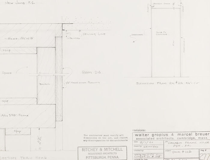
This image displays a set of architectural drawings with annotations, measurements, and revision notes. The drawings are created in pencil on a white background, featuring a mix of lined sketches and written notes that detail aspects of a construction element or architectural detail. On the left side of the image is a cross-sectional view of a structure, labelled "T.S. SECTION THRU HEAD," showing different layers and components such as "Metal Jamb E.S.," "Head Jamb," "Threshold," and "New Storage Space." These labels indicate the parts of a door or window frame. There are hashed areas representing materials and arrows indicating directions or positions. On the right side, there is a drawing labelled "ELEVATION FROM RM 216," which refers to a view of a wall or door from room 216. This drawing includes vertical measurements and identifies parts like the "Existing Steel Frame," "Door," "Ceiling Line," and noting different reference points like "C.L. of Existing Frame." At the bottom right corner of the drawings, there is a box with the project title and names: "Walter Gropius & Marcel Breuer & Associated Architects, Cambridge, Mass." Below is a box for "Revisions," with dates and descriptions of changes made, indicating that this is an official working document from a professional architectural practice. There is also a firm's stamp from "RITCHEY & MITCHELL REGISTERED ARCHITECTS PITTSBURGH, PENNA." indicating the location of the architectural firm involved. The sketch is technical and precise, intended for professionals involved in the construction or renovation of the design detailed in the drawing. The document is number 277, suggesting it is part of a larger set of plans.
Created by gpt-4o-2024-05-13 on 2025-03-06
The image is an architectural drawing, which includes detailed sections and elevations of a building's wall and door construction. The drawing contains various specifications and labels indicating different parts of the structure, such as the wall, door jamb, stops, and other construction elements. - The left side of the drawing shows a "F.S. SECTION THRU HEAD," which appears to be a detailed cross-section view through the upper part of a door or window opening. The section includes different materials and dimensions, with callouts like "New Jamb F.G.," "Head, 13/4"x6 1/8", and "1/2" Plyboard". - There is a notation for a "New Storage Space" as well as labels indicating materials like "Gypsum," "Plaster," and dimensions for various parts of the wall and frame. - The right side of the drawing shows an elevation view labeled "ELEVATION FROM RM #216" which demonstrates the frontal construction outline from Room 216. This includes the door location, frame details, and the adjoining wall layout. - Details such as "1/4" Hardwood Plyboard," "Plaster," and "Ceiling Line" are indicated. - The lower right corner holds a title block that provides information about the project, including the architects involved - Walter Gropius & Marcel Breuer, the drawing number (277), the scale, and other notes regarding revisions, date, and drafter. The drawing demonstrates a high level of detail necessary for construction and refurbishment projects, focusing on the precise fitting and materials required for proper assembly.
Anthropic Claude
Created by claude-3-haiku-20240307 on 2024-12-30
The image appears to be an architectural drawing or blueprint for a building. It contains various technical details and measurements, including floor plans, elevations, and annotations. The drawing seems to be for a room or structure labeled "Room 216". There are references to materials and construction, such as a "1/4 stop" and "Ceiling Line". The drawing is signed by "Ritchey & Mitchell, Registered Architects, Pittsburgh, Penna."
Created by claude-3-opus-20240229 on 2024-12-30
The image shows an architectural blueprint or floor plan for a residence designed by Ritchey & Mitchell Registered Architects in Pittsburgh, Pennsylvania. The plan indicates the layout and dimensions of various rooms including a living room, dining room, kitchen, bathroom, and several bedrooms. Additional notes specify details like elevations, doors, windows, and a "water coping & marcel brewer associated architects" revision.
Created by claude-3-5-sonnet-20241022 on 2024-12-30
This is an architectural drawing showing technical section details and elevations. The drawing appears to be created by Ritchey & Mitchell, Registered Architects from Pittsburgh, Pennsylvania, in collaboration with Walter Gropius and Marcel Breuer. The drawing includes both plan and section views, with detailed measurements and notations. It shows structural elements like wall sections, framing details, and ceiling lines. The drawing uses standard architectural conventions with clean, precise lines and includes notations for different components and materials. There's a section labeled "Room 216" and various technical specifications. The drawing number appears to be "277" and includes revision notes at the bottom of the sheet.
Meta Llama
Created by us.meta.llama3-2-11b-instruct-v1:0 on 2025-03-13
The image presents a detailed architectural drawing, likely a floor plan or elevation, showcasing various rooms and spaces within a building. The drawing is rendered in pencil on white paper, featuring handwritten notes and measurements. **Key Features:** * **Title and Information:** In the bottom-right corner, the title "revisions" is accompanied by the names "walter gropius & marcel breuer associated architects cambridge, mass." and the date "5/4/30." Below this, a box contains the text "RITCHEY & MITCHELL REGISTERED ARCHITECTS PITTSBURGH, PENNA." * **Room Labels and Measurements:** Throughout the drawing, rooms are labeled with abbreviations, such as "F.S." for "floor space," and measurements are provided in feet and inches. For example, Room 216 is marked with a measurement of 12' x 10'. * **Wall and Door Details:** The drawing includes detailed information about walls, doors, and other architectural features. For instance, a wall is labeled as "WALL LINE - HEAVY," and a door is marked with the measurement "Door # 222" and the label "Door # 222." * **Elevation and Corridor:** The drawing also includes an elevation of a wall, which is labeled "ELEVATION FROM RM #216 #4' 1/2"" and features a corridor with a door at the end. * **Scale and Grid:** The drawing appears to be scaled to 1/4" = 1'-0", with a grid pattern visible in the background. This suggests that the drawing is intended for use in a larger architectural context. **Overall Impression:** The drawing provides a comprehensive view of the building's layout, including various rooms, corridors, and architectural features. The inclusion of measurements and labels suggests that the drawing is intended for use in a professional or technical context, such as construction or renovation planning.
Created by us.meta.llama3-2-90b-instruct-v1:0 on 2025-03-13
The image depicts a detailed architectural drawing of a room, likely part of a larger building plan. The drawing is rendered in pencil on white paper and features various elements, including walls, doors, windows, and other architectural features. **Key Features:** * **Walls:** The room has several walls, each labeled with its corresponding dimensions. * **Doors:** There are two doors visible in the drawing, one leading to a hallway and the other to a storage space. * **Windows:** A window is located on the left side of the room, providing natural light. * **Storage Space:** A storage space is located adjacent to the room, accessible through a door. * **Hallway:** A hallway connects the room to other areas of the building. * **Dimensions:** The drawing includes detailed dimensions for each element, ensuring accuracy in construction. * **Labels:** Various labels are used throughout the drawing to identify different components, such as "New Jamb F.S." and "Ceiling Line." * **Elevation:** An elevation view of the room is provided, showing the height and layout of the space. * **Revisions:** A section at the bottom right corner indicates revisions made by Walter Gropius & Marcel Breuer, associated architects from Cambridge, Massachusetts. * **Date:** The date "2/11/69" is written in the bottom-right corner, indicating when the revisions were made. * **Client:** The client's name, "Georgia Pacific," is listed along with their address in Atlanta, Georgia. * **Project Number:** The project number "277" is displayed in the bottom-right corner. **Conclusion:** In summary, this architectural drawing provides a comprehensive view of a room's design, including its layout, dimensions, and features. The inclusion of revisions and client information suggests that this drawing was created for a specific project, likely a commercial or residential development.
Amazon Nova
Created by amazon.nova-lite-v1:0 on 2025-01-13
The image appears to be an architectural drawing or blueprint. It shows a floor plan with various sections and dimensions labeled. The drawing includes text and annotations in the bottom right corner, indicating it is a revision of a previous version. The drawing is labeled "F.S. SECTION THRU HEAD" and includes dimensions such as "134'7/8"" and "134'5/8'". The drawing also includes the names of the architects, Walter Gropius and Marcel Breuer, and the location of the project, Cambridge, Massachusetts.
Created by amazon.nova-pro-v1:0 on 2025-01-13
The image is a detailed architectural drawing on a white sheet of paper. The drawing is divided into sections, each depicting different aspects of a building's structure. The top section features a wall with measurements and labels, including "WALL LINE VENTY" and "1/2" HARDWOOD PLYWOOD." Below this, there is a floor plan with dimensions and annotations such as "New Jamb F.S." and "HEAD 13/4"x61/8." The center section shows a detailed elevation with labels like "BELING LINE" and "1/2" STOP." The bottom section includes additional floor plans and elevations with labels such as "NEW STORAGE SPACE" and "ROOM 216." The right side of the drawing contains a revision log with dates, names, and changes made to the design. The drawing is signed by "WALTER GROPIUS & MARCEL BREUER" and "RITCHEY & MITCHELL," indicating the architects involved in the project.
Text analysis
Amazon