Machine Generated Data
Tags
Color Analysis
Feature analysis
Amazon
Clarifai

Clarifai
| Whiteboard | 76.9% | |
Categories
Imagga
created on 2018-03-22
| text visuals | 99.8% | |
| paintings art | 0.2% | |
Captions
Microsoft
created by unknown on 2018-03-22
| a close up of text on a whiteboard | 80.9% | |
| a close up of a whiteboard | 78.1% | |
| close up of text on a whiteboard | 78% | |
Clarifai
No captions written
Salesforce
Created by general-english-image-caption-blip on 2025-05-11
a photograph of a drawing of a plan for a house
Created by general-english-image-caption-blip-2 on 2025-06-28
a drawing of a house with a staircase and stairs
OpenAI GPT
Created by gpt-4o-2024-05-13 on 2025-03-07
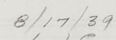
The image is an architectural drawing created by the architect firm Ritchey & Mitchell Architects from Pittsburgh, Pennsylvania, in collaboration with the associated architects Walter Gropius & Marcel Breuer from Cambridge, Massachusetts. The drawing features detailed plans for proposed alterations, identified as "Proposed Alteration Game RM. PLAN" and "Proposed Alteration N.W. ELEV."
The drawing includes annotations and measurements for the alterations. The upper section shows a plan view detailing a staircase and the layout of a room, presumably the game room. The annotations next to this show dimensions and specific design changes.
In the lower section, a side elevation view is depicted, showcasing the exterior façade and internal layout. This elevation view includes features such as windows, doors, chimneys, and changes to structural elements. Notably, there is a detailed staircase design and annotations pointing to various parts of the structure.
In the bottom-right corner of the drawing is a title block providing information about the firms involved and revisions made. It mentions revisions dated 2-5-58 and 3-5-58, providing an insight into the timeline of the alterations.
Overall, the drawing is a technical blueprint illustrating planned structural and design alterations to an existing architectural project.
Created by gpt-4 on 2025-03-07
This is an architectural drawing featuring plans and elevations of a proposed residential building. It shows meticulous detail with clearly labelled sections, measurements, and scale denotations for various parts of the architecture. You can see distinct components such as walls, windows, stairs, and floors represented schematically.
On the bottom right of the drawing, there is a box with text that appears to be the title block, which typically includes information about the project, architects, and relevant details such as the drawing's scale and date. There's also a revision block on the right side with names and revision details, which suggests that multiple professionals, possibly architects or designers, have contributed to the development of this design.
Anthropic Claude
Created by us.anthropic.claude-3-5-sonnet-20241022-v2:0 on 2025-06-25
This image shows an architectural drawing - specifically elevation plans for what appears to be the Ritchey & Mitchell project in Pittsburgh, Pennsylvania. The drawing consists of two elevation views showing the exterior profiles of a building design. The plans are done in a technical drafting style with clean lines and measurements indicated. The architects listed on the drawing are Walter Gropius & Marcel Breuer, Associated Architects from Cambridge, Massachusetts. The drawing includes both a proposed elevation and other architectural details, with various horizontal and vertical elements clearly delineated. The plans appear to be dated and include revision notes. The drawing style is typical of mid-century modern architectural documentation, with precise linework and professional drafting standards.
Created by claude-3-haiku-20240307 on 2024-12-30
The image appears to be an architectural drawing or blueprint of a proposed building or structure. It contains various technical diagrams, measurements, and annotations, suggesting it is a detailed engineering or design plan. The drawing shows multiple views, including a side elevation and a floor plan, with various structural elements and features depicted. While the image does not contain any human faces, it provides a comprehensive technical illustration of the proposed design.
Created by claude-3-5-sonnet-20241022 on 2024-12-30
This is an architectural drawing showing proposed alterations, likely for a building renovation project. The image contains two elevation views - one at the top showing what appears to be a stair detail with curved elements, and a larger elevation view below showing a more detailed facade treatment.
The drawing is done in a professional architectural style with clean lines and includes various architectural elements like parapet walls, windows, and structural details. There are some measurements and notes included on the drawing, though they're not all clearly legible in this image.
The drawing appears to be from an architectural firm - Walter Gropius & Marcel Breuer Associated Architects from Cambridge, Massachusetts, in collaboration with Ritchey & Mitchell from Pittsburgh, Pennsylvania, as indicated in the title block at the bottom of the sheet.
The drawing has a specific drawing number and appears to be part of a larger set of construction documents. It's rendered in pencil on what looks like architectural drawing paper, typical of professional architectural documentation from this era.
Meta Llama
Created by us.meta.llama3-2-11b-instruct-v1:0 on 2025-03-15
The image presents a technical drawing of a building's interior, showcasing the layout and design of the space. The drawing is rendered in pencil on white paper, with a focus on the staircase and surrounding areas.
Key Features:
- Staircase: The staircase is prominently featured in the top half of the drawing, with its shape and dimensions clearly defined. The staircase appears to be a curved, open design that connects two levels of the building.
- Surrounding Areas: The surrounding areas are depicted in detail, including the walls, floors, and ceilings. The drawing also shows the location of doors, windows, and other architectural features.
- Labels and Annotations: The drawing includes labels and annotations that provide additional information about the design. These labels likely indicate the type of material used for each element, such as wood or metal.
- Scale and Measurements: The drawing includes a scale and measurements, which allow the viewer to understand the proportions and dimensions of the space. This information is essential for architects, engineers, and contractors who need to build the space according to the design.
- Overall Design: The overall design of the space is modern and sleek, with clean lines and minimal ornamentation. The use of natural light and the emphasis on functionality suggest that the space is intended for commercial or office use.
Conclusion:
The technical drawing provides a detailed and accurate representation of the building's interior, allowing architects, engineers, and contractors to understand the design and build the space accordingly. The drawing's focus on functionality and natural light suggests that the space is intended for commercial or office use, and the modern design aesthetic will likely appeal to a wide range of users.
Created by us.meta.llama3-2-90b-instruct-v1:0 on 2025-03-15
The image presents a detailed architectural drawing of a building's floor plan, showcasing the meticulous design and layout of the structure. The drawing is rendered in black ink on white paper, with precise lines and annotations that provide valuable insights into the building's architecture.
Key Features:
- Floor Plan: The drawing depicts the floor plan of the building, including various rooms, corridors, and staircases.
- Annotations: The drawing includes annotations and notes that provide additional information about the building's design and construction.
- Scale: The drawing is drawn to scale, allowing for accurate measurements and calculations.
- Architectural Details: The drawing includes detailed architectural features such as windows, doors, and columns.
- Revision History: The drawing includes a revision history, indicating changes made to the original design.
Conclusion:
The image provides a comprehensive view of the building's floor plan, highlighting the attention to detail and precision that went into its design. The annotations and notes add an extra layer of depth to the drawing, providing valuable context and information about the building's architecture. Overall, the image is a testament to the skill and craftsmanship of the architects who created it.
Amazon Nova
Created by amazon.nova-lite-v1:0 on 2025-01-12
The image is a technical architectural drawing, possibly a floor plan or a section view of a building. The drawing is detailed, showing various structural elements and annotations. It includes the text "PROPOSED ALTERATION-GAME RM." at the top, indicating that the drawing pertains to proposed changes or additions to a game room. The drawing is dated "8/19/64," suggesting it is from the mid-20th century. The drawing features several architectural elements such as walls, doors, windows, and possibly staircases or other structural components. There are also annotations and measurements throughout the drawing, indicating dimensions and specific details of the proposed alterations. The drawing is labeled with the name "RITCHEY & MITCHELL REGISTERED ARCHITECTS PITTSBURGH, PENNA." at the bottom, identifying the architectural firm responsible for the design. The drawing is part of a larger set of documents or plans, as indicated by the reference to "REVISIONS" and the mention of "WALTER GROPIUS & MARCEL BREUWER" associated architects in Cambridge, Massachusetts. The drawing is meticulous and professional, reflecting the standards of architectural documentation from that era.
Created by amazon.nova-pro-v1:0 on 2025-01-12
The image shows a technical drawing of a building. The drawing is made of lines and shapes that represent different parts of the building, such as walls, floors, and stairs. The drawing is labeled with text that provides information about the building, such as the date, the architect, and the contractor. The drawing also includes a table with details about the building's dimensions and materials. The image is in black and white, which is common for technical drawings.
Google Gemini
Created by gemini-2.0-flash on 2025-05-25
Here's a description of the image based on the provided information:
Overall:
The image shows a technical architectural drawing, specifically a proposed alteration plan for a building. It appears to be a blueprint or similar technical document due to its pale background and fine lines.
Main Elements:
- Elevations: The drawing includes a "M.W. ELEV" (likely referring to a Northwest elevation) of the building. This view provides a side-on perspective, showing the height and arrangement of different levels, windows, and architectural features.
- Proposed Alteration - Game Room: Above the elevation, there's a smaller plan labeled "PROPOSED ALTERATION - GAME RM." This likely details the intended changes to a specific room (the game room) within the building, including its layout and relationship to a staircase and potentially a lounge or other seating area as the furniture/seating areas are depicted by small circles.
- Dimensions: Numerous lines and annotations indicate precise dimensions and measurements throughout the drawing.
Text and Titles:
- The titles "PROPOSED ALTERATION - GAME RM." and "PROPOSED ALTERATION M.W. ELEV." are prominently displayed, indicating the subject of each section of the drawing.
- Dates are included near the titles.
- A footer or stamp identifies "RITCHEY & MITCHELL, REGISTERED ARCHITECTS, PITTSBURGH, PENNA." This indicates the architectural firm responsible for the design.
- "Walter Gropius & Marcel Breuer Associated Architects, Cambridge, Mass" are listed as revisions.
- "RESIDENCE FOR AIRS. CECELIA FRANK"
In essence: The image is a professional architectural drawing outlining proposed modifications to a building. It contains detailed elevation views, alteration plans for a game room, dimensions, and credits to the involved architects and architectural firm.
Created by gemini-2.0-flash-lite on 2025-05-25
This is an architectural drawing or blueprint, rendered in fine, technical lines. It's on a sheet of paper that looks slightly aged, suggesting it's an older plan. Here's a breakdown:
- Layout: The drawing presents a top-down plan of a section of a building, likely an alteration or addition. Above the main section is a detailed plan, showing the plan of a room. A set of stairs and a curved design are in the same plan. The lower drawing, likely an elevation view, showing a side or front view of the building, with multiple windows. The building has a flat roof.
- Annotations and Markings: There are numerous annotations, dimensions, and labels indicating the different components of the building. There are labels such as "NEW BAROIST" and "NEW GARRET" along with dimension lines, adding to the technical nature of the drawing.
- Title Block: In the bottom right, there's a title block that contains the architects' information, project details, and other essential data, like the date of the drawing, the architects are named Walter Gropius and Marcel Breuer. The project name is listed as "RESIDENCE FOR MRS. CECELIA FRANK"
- Overall Impression: The drawing's detailed nature and precise annotations suggest a plan intended for construction purposes, likely for a residential alteration project.
Mistral Pixtral
Created by us.mistral.pixtral-large-2502-v1:0 on 2025-05-30
The image is an architectural drawing, specifically a floor plan, that appears to be a proposed alteration for a building. Here are the key details:
Drawing Layout:
- The drawing is divided into two main sections. The upper section shows a smaller floor plan, while the lower section displays a larger and more detailed floor plan.
- Both sections include various rooms and spaces, with walls, doors, and other structural elements clearly marked.
Labels and Annotations:
- The drawing includes labels for different areas such as "public foyer," "lobby," "men's restroom," "women's restroom," "men's locker room," and "women's locker room."
- There are also annotations indicating specific dimensions and measurements, such as "2'-6" and "6'-0"."
Scale and Date:
- The scale of the drawing is noted as "2'-0" and "6'-0"."
- The date on the drawing is "6/24/65."
Architects and Firms:
- The drawing is attributed to Walter Gropius and Marcel Breuer, both notable architects.
- The architectural firm involved is "The Architects Collaborative" from Cambridge, Massachusetts.
- The drawing was prepared by "Ritchey & Mitchell," registered architects from Pittsburgh, Pennsylvania.
Revisions and Approval:
- There is a note indicating that the contractor must verify all dimensions and that the architects are not responsible for any discrepancies.
- The drawing includes a revision section with dates and initials indicating changes or approvals.
Additional Notes:
- The drawing number is "109."
- There is a stamp or signature area at the bottom right, likely for approval or verification purposes.
Overall, the image represents a detailed architectural plan for alterations to a building, with specific attention to public and private spaces, restrooms, and locker rooms. The drawing is meticulously labeled and includes important information for construction and verification purposes.
Qwen
Created by Qwen/Qwen2.5-VL-7B-Instruct on 2025-07-20
This image is an architectural drawing, specifically a proposed alteration elevation for a game room and the northwest (N.W.) elevation of a building. The drawing includes detailed annotations with measurements, dimensions, and notes such as "FIN. SECOND FLOOR," "FIN. FIRST FLOOR," and "FIN. GROUND FLOOR." The drawing is signed by L.J.C. and has a date of 8/17/39. It also includes a note about verifying all dimensions on the job and reporting any discrepancies to the architects.
The architects listed on the drawing are Walter Gropius and Marcel Breuer, with their practice being associated with Ritchey & Mitchell, Registered Architects, located in Pittsburgh, Pennsylvania. The project is titled "RESIDENCE FOR MRS. CECILIA FRANK" and is a proposed alteration elevation. The scale of the drawing is 1/4" = 1'-0".
The drawing includes elements such as chimneys, mesh parapets, and a staircase, indicating the layout and design details of the building's exterior.
Created by Qwen/Qwen2.5-VL-72B-Instruct on 2025-07-20
This image is an architectural drawing titled "PROPOSED ALTERATION - GAME RM." and "PROPOSED ALTERATION N.W. ELEV." The drawing is dated August 17, 1939, and is signed by L.J.C.
The top part of the drawing shows a plan view of a game room, with various dimensions and details such as a fireplace and a staircase leading to an upper level. The plan includes measurements and notes for the layout and features of the room.
The bottom part of the drawing shows the northwest elevation of the building, with details of the exterior walls, windows, and a chimney. The elevation includes dimensions and notes for the construction materials and finishes, such as "RUBBLE STONE" and "MESH PARAPET."
The drawing is by Walter Gropius & Marcel Breuer, associated architects based in Cambridge, Massachusetts, for the residence of Mrs. Cecelia Frank. The drawing number is 109, and the scale is 1/4" = 1'-0". The drawing was checked by L.J.C. and the date of the revision is August 22, 1939. The architectural firm Ritchey & Mitchell, registered architects from Pittsburgh, Pennsylvania, is also mentioned on the drawing.
Text analysis
Amazon