Machine Generated Data
Tags
Color Analysis
Feature analysis
Amazon
| Passport | 70.5% | |
Categories
Imagga
| text visuals | 99.8% | |
| paintings art | 0.2% | |
Captions
Microsoft
created on 2018-03-22
| a close up of text on a whiteboard | 78.6% | |
| a close up of a whiteboard | 76.4% | |
| close up of text on a whiteboard | 76% | |
OpenAI GPT
Created by gpt-4 on 2025-03-06
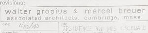
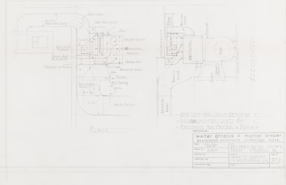
The image displays an architectural drawing or blueprint, showing the detailed layout for a particular section of a building. Various handwritten notes and measurements indicate the specific dimensions, materials, and construction details needed for the space. The drawing seems to include plans for air handling units, denoted by references to "return air" and "fresh air," implying a ventilation system. The text at the bottom provides context for the drawing, identifying it as "ONE LINE MECHANICAL DETAIL of DEHUMIDIFIER DUCTS ETC." for a residence, with specific names mentioned (which we will not disclose to respect privacy). This indicates that the drawing relates to the HVAC (heating, ventilation, and air conditioning) system of the residence. The architects listed are Walter Gropius & Marcel Breuer, associated architects based in Cambridge, Massachusetts, which suggests that this blueprint could be historically significant, as both individuals are prominent figures in modern architecture. Additional annotations like "checked by," "drawn by," and "date" along with various initials and a date, are typical of architectural practices, indicating the professionals involved in the creation and review of the drawing and the date it was drafted or revised. The number "201" could be a reference to either a drawing number or project code used within the architect's filing system.
Created by gpt-4o-2024-05-13 on 2025-03-06
This image is a detailed architectural drawing of ductwork and air conditioning equipment for a dehumidifier system. The drawing is done in a meticulous technical style, commonly associated with blueprints used in construction and engineering. The layout includes two main views: a plan view (a top-down perspective) on the left side and an elevated view (a side perspective) on the right side. The plan view illustrates the arrangement of ducts, specifying measurements and connections, while the elevation view provides a side profile with measurements focusing on vertical aspects. Key annotations are made throughout, labeling components like splitters, canvas goints, air inlet/outlet, fans, exhaust, return air train, filters, and casings. The labels include dimensions, material requirements, and notes on installation. In the lower right corner, there is a title block containing the name of the project, the architects, the date, and other project management details. The architects named are Walter Gropius and Marcel Breuer from the associated architects firm located in Cambridge, Massachusetts. The client for this project is noted as Mrs. Cecilia Fanelli from Pittsburgh, Pennsylvania. The drawing is titled "LAYOUT OF EQUIPMENT IN AIR CONDITIONING RM" and is marked with the sheet number 201. The detailed notes at the bottom of the elevations indicate various aspects of duct and equipment configurations, likely offering insights into the material type, scale, and functional instructions to ensure precise construction and installation.
Anthropic Claude
Created by claude-3-haiku-20240307 on 2024-12-30
This image appears to be an architectural floor plan or blueprint. It contains detailed technical drawings and measurements for various rooms, spaces, and structural elements. The plan includes labels and annotations indicating different features and components of the building design. The overall layout and configuration suggest this is a residential or commercial property plan, though without more context, I cannot determine the specific purpose or location of the structure depicted.
Created by claude-3-opus-20240229 on 2024-12-30
The image shows architectural plans or blueprints for what appears to be a building or structure named "Walter Gropius & Marcel Breuer Associated Architects, Cambridge, Mass." The plans include various annotated diagrams and measurements depicting floor plans, elevations, and construction details. The schematic drawings utilize thin lines and are rendered on grid paper. A rectangular stamp at the bottom provides the name and location of the associated architects.
Created by claude-3-5-sonnet-20241022 on 2024-12-30
This is an architectural drawing/blueprint that appears to be created by Walter Gropius & Marcel Breuer Associated Architects from Cambridge, Massachusetts. The drawing shows various technical details including floor plans and what appears to be HVAC or mechanical equipment layouts. The plan view includes dimensions and annotations, with notations for elements like "Dry Air Outlet" and ventilation components. The drawing is dated 1/22/40 and includes title block information in the lower right corner. It's a detailed technical document that appears to be related to the layout of mechanical systems or air conditioning equipment for a building project.
Meta Llama
Created by us.meta.llama3-2-11b-instruct-v1:0 on 2025-03-13
The image is a technical drawing of a plane, with various components labeled and detailed. The drawing appears to be a blueprint or schematic for an aircraft, showing the layout of the plane's interior and exterior features. * The drawing is done in pencil on white paper. * It features a detailed diagram of the plane's structure, including the fuselage, wings, tail, and control surfaces. * The drawing includes labels and annotations to identify different parts of the plane, such as the cockpit, engines, and landing gear. * The drawing also shows the plane's dimensions and proportions, including the length, width, and height of the fuselage. * The drawing is signed by the architect, Walter Gropius and Marcel Breuer. * The signature is located in the bottom-right corner of the drawing. * The signature indicates that the drawing was created by the two architects who were associated with the project. * The drawing is dated 1922/30. * The date is located in the bottom-right corner of the drawing. * The date suggests that the drawing was created during the 1920s or early 1930s. * The drawing is labeled "Plane" in the center of the page. * The label is written in large letters and is easily visible. * The label indicates that the drawing is a representation of an airplane. Overall, the image provides a detailed and technical view of a plane's design and construction. The drawing is likely a blueprint or schematic used by architects or engineers to plan and build the plane.
Created by us.meta.llama3-2-90b-instruct-v1:0 on 2025-03-13
The image depicts a technical drawing of a building's floor plan, likely created for architectural or engineering purposes. The drawing is rendered in black ink on white paper and features various symbols, labels, and measurements that provide detailed information about the building's layout and design. **Key Features:** * **Floor Plan:** The central element of the image is the floor plan, which shows the layout of the building's rooms, corridors, and other spaces. * **Symbols and Labels:** Throughout the drawing, various symbols and labels are used to indicate different features such as doors, windows, walls, and ceilings. * **Measurements:** The drawing includes measurements and dimensions of the building's components, providing precise information for construction or renovation purposes. * **Architectural Details:** The image also includes architectural details such as staircases, elevators, and other structural elements. * **Text and Annotations:** In addition to the visual elements, the drawing contains text and annotations that provide additional context and information about the building's design and functionality. **Overall Impression:** The image presents a comprehensive and detailed representation of a building's floor plan, showcasing the careful planning and attention to detail that goes into designing and constructing a structure. The use of symbols, labels, and measurements ensures that the drawing is clear and easy to understand, making it a valuable resource for architects, engineers, and builders.
Amazon Nova
Created by amazon.nova-lite-v1:0 on 2025-02-25
The image appears to be an architectural drawing or blueprint for a residence. It shows various details and plans for the building, including: - Floor plans with room layouts and dimensions - Elevations showing the exterior design and dimensions - Sections and details of specific components like ductwork, ventilation systems, and equipment layouts - Notes and labels indicating materials, dimensions, and other specifications The drawing is labeled as being for the "Residence for Mrs. Cecilia K. Feark" in Pittsburgh, PA. It is signed by the architect, Walter Gropius, and his associate Marcel Breuer. The drawing is dated July 24, 1940. The image provides a detailed view of the architectural design and construction plans for this residential building, showcasing the work of the renowned architects Walter Gropius and Marcel Breuer during that time period.
Created by amazon.nova-pro-v1:0 on 2025-02-25
The image is a black-and-white architectural drawing on a white background. It includes a floor plan, an elevation, and a detailed section of a mechanical system, likely for a residential or commercial building. The drawing is labeled "Walter Gropius & Marcel Breuer," indicating the architects involved. The date of the drawing is 12/2/40, and it was drawn by C.A.W. The drawing includes dimensions, annotations, and a legend explaining the symbols used. The mechanical system appears to be a heating, ventilation, and air conditioning (HVAC) system, with components such as ducts, vents, and equipment labeled. The drawing is titled "One Half Inch Scale Detail of Fan-Dehumidifier Ducts & Equipment for Residence for Mrs. Cecila Feark," suggesting it is a detailed plan for a specific residential project.
Text analysis
Amazon