Machine Generated Data
Tags
Color Analysis
Categories
Imagga
| text visuals | 100% | |
Captions
Microsoft
created on 2018-03-22
| a close up of text on a white surface | 74.4% | |
| a close up of text on a table | 67.2% | |
| a screenshot of text | 67.1% | |
OpenAI GPT
Created by gpt-4 on 2025-03-06
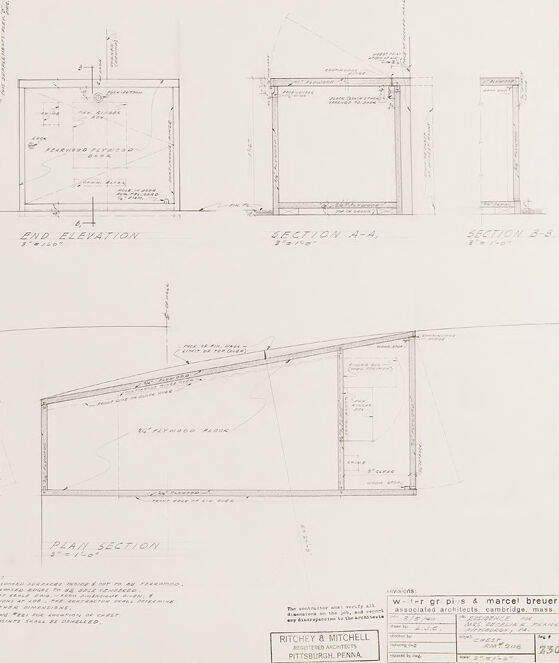
The image presents a set of architectural drawings or blueprints, shown in a light sketch style on what appears to be a large sheet of paper. These drawings feature various elevations and sections of a building, providing a detailed representation of the structure's design from multiple perspectives. In the left area of the image are two elevation views labeled "FRONT ELEVATION" and "END ELEVATION," which show the building's outward appearance from the front and side. To the right, there are two sectional drawings, labeled "SECTION A-A" and "SECTION B-B," which depict the building as if it were cut along specific planes, revealing the internal structural elements and spatial layout. The drawings are annotated with numerous lines, dimensions, notes, and labels, providing precise measurements and construction details that would be necessary for building the structure. Text and symbols throughout the image indicate the scale, various materials to be used, and specific design features. At the bottom right of the image, there is a title block with text that seems to include the names of individuals or entities associated with the project (although we should refrain from explicitly identifying any persons), as well as the location and other relevant project information.
Created by gpt-4o-2024-05-13 on 2025-03-06
The image is a detailed architectural blueprint for a projection booth. The blueprint includes various views and sections of the booth, each meticulously labeled and dimensioned. 1. **Front Elevation** (upper left): This view shows the front side of the booth, indicating the exterior appearance and placement of elements such as doors and windows. 2. **End Elevation** (upper middle): This view presents the side profile of the booth, providing details on the vertical elements and giving a sense of the overall height and structure. 3. **Section A-A** (upper right): This cross-sectional view, sliced through a specific vertical plane, reveals the internal configuration and components within the booth, such as walls and equipment. 4. **Section B-B** (upper right, next to Section A-A): Another cross-sectional view, typically showing a cut through a different part of the booth to illustrate areas not covered in Section A-A. 5. **Plan** (lower left): This is a top-down view, or floor plan, detailing the layout of the interior space. It usually marks the positioning of walls, doors, and other significant features from an aerial perspective. 6. **Plan Section** (lower right): A detailed side section, similar to the cross-sectional views, but potentially depicting additional layers or materials involved in the construction. At the bottom right of the blueprint is a title block containing project details such as the name "Ritchey & Mitchell" with the note "Associated Architects, Cambridge, Mass.," and mentions of "William P. Gris" and "Marcel Breuer," suggesting their association with the project. The title block also includes miscellaneous project notes and the date "3/13/58." Overall, the blueprint provides a comprehensive technical plan for the construction of the projection booth, showcasing its dimensions, materials, and structural components.
Anthropic Claude
Created by claude-3-haiku-20240307 on 2024-12-30
This image appears to be a set of architectural plans or technical drawings. It shows various elevations, sections, and plan views of what looks like a building or structure. The drawings are filled with detailed measurements, annotations, and technical specifications, indicating this is likely an engineering or construction document. Without any identifying information about the specific building or people involved, I can only describe the content of the image itself, which consists of these intricate technical drawings and diagrams.
Created by claude-3-opus-20240229 on 2024-12-30
The image shows architectural plans or blueprints drawn on drafting paper. It contains several rectangular sections representing different elevations or views of a structure. The drawings include measurements and annotations to specify dimensions and details. Based on the title in the bottom right, this appears to be plans for a "Ranch Breeder Poultry System Breeding Pens". The plans depict the layout and construction of some kind of agricultural building or enclosure for poultry breeding.
Created by claude-3-5-sonnet-20241022 on 2024-12-30
This image shows architectural drawings or blueprints with various elevations and sections of what appears to be a building or structure. The drawings include: 1. Front Elevation 2. End Elevation 3. Section A-A 4. Section B-B 5. Plan views 6. Cross-sectional views The drawings are done in a technical drafting style with clean lines and measurements indicated. They appear to be professional architectural plans, with a title block visible in the bottom right corner mentioning "Pittsburgh, Penna." The drawings show different angles and perspectives of what seems to be a modernist or minimalist structure with straight lines and angular features. The plans include notes and specifications, though the details are not clearly legible in this image. The overall presentation is typical of mid-century architectural documentation, with multiple views provided to give complete construction information to builders.
Meta Llama
Created by us.meta.llama3-2-11b-instruct-v1:0 on 2025-03-13
The image is a technical drawing of a building's elevation and plan, created by Ritchey & Mitchell, Registered Architects, Pittsburgh, PA. The drawing is dated 1930 and features a detailed sketch of the building's front and side elevations, as well as its floor plan. **Elevation Drawings:** * The front elevation is shown on the top left, with the building's facade facing the viewer. * The side elevation is depicted on the top right, with the building's long side facing the viewer. * Both elevations include measurements and notes, indicating the location of windows, doors, and other architectural features. **Plan Drawing:** * The floor plan is shown on the bottom half of the page, with the building's interior layout displayed in a two-dimensional format. * The plan includes measurements and notes, indicating the location of rooms, corridors, and other interior features. **Additional Details:** * The drawing includes a key or legend in the bottom-right corner, which explains the symbols and abbreviations used throughout the drawing. * The drawing also includes a scale bar, which allows the viewer to measure the size of the building and its features. * The drawing is signed by the architects, Ritchey & Mitchell, and includes their business information, including their address and phone number. Overall, the image provides a detailed and accurate representation of the building's design and layout, making it a valuable resource for architects, engineers, and construction professionals.
Created by us.meta.llama3-2-90b-instruct-v1:0 on 2025-03-13
The image presents a technical drawing of a building's architectural plans, featuring various sections and elevations. The top section showcases the front elevation, end elevation, and section A-A, while the bottom section displays the plan and section. The drawing is rendered in black ink on white paper, with precise measurements and annotations throughout. In the bottom-right corner, a rectangular box contains the names "Ritchey & Mitchell" and "Wm. G.F. Price & Marcel Breuer," accompanied by their respective addresses in Pittsburgh, Pennsylvania, and Cambridge, Massachusetts. A smaller box to the right lists the drawing number, date, and scale, although the text is too small to be legible. Overall, the image provides a detailed and informative representation of the building's design, highlighting its architectural features and specifications.
Amazon Nova
Created by amazon.nova-lite-v1:0 on 2025-01-13
This image is a blueprint of a house. The blueprint includes a plan section, front elevation, end elevation, and section A-A and B-B. The plan section shows the layout of the house, including the placement of walls, doors, and windows. The front elevation shows the exterior of the house from the front, while the end elevation shows the exterior from the end. The sections A-A and B-B show the interior of the house, including the placement of walls, doors, and windows. The blueprint also includes notes and measurements for the construction of the house.
Created by amazon.nova-pro-v1:0 on 2025-01-13
The image depicts a blueprint of a building with multiple sections. The top section is labeled "FRONT ELEVATION," and the bottom section is labeled "END ELEVATION." The blueprint also includes a "PLAN SECTION" with dimensions and measurements. The blueprint appears to be a detailed plan for the construction of a building, with specific instructions and measurements for each section. The blueprint is drawn in black ink on white paper, and the text is written in a clear and legible font.
Text analysis
Amazon