Machine Generated Data
Tags
Color Analysis
Feature analysis
Amazon
Clarifai

Clarifai
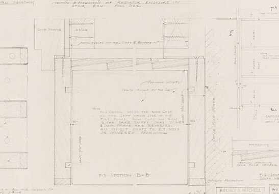
| Envelope | 52% | |
Categories
Imagga
created on 2018-03-22
| text visuals | 100% | |
Captions
Microsoft
created by unknown on 2018-03-22
| a screenshot of a computer | 67.4% | |
| a close up of a computer screen with text | 60.3% | |
| a computer screen with text | 60.2% | |
Salesforce
Created by general-english-image-caption-blip-2 on 2025-06-28
a drawing of a kitchen and a kitchen island
Created by general-english-image-caption-blip on 2025-05-04
a photograph of a drawing of a plan for a house
OpenAI GPT
Created by gpt-4 on 2025-03-08
The image displays a sheet of architectural drawings or plans with various detail sketches. These drawings are precise, technical, and annotated, possibly for the construction or detailing of a building component. The sketches contain dimensions and written notes that explain specific aspects of the design or construction. The drawings are shown in different orientations and scales, providing various views and cross-sections.
There are labels such as "Imbedment in floor," "Typical opening detail in floor slab," and "Dowels." These indicate details for embedding components into a floor and the use of dowels, which are likely parts of the structural connections. Cross-sections labeled "Section A-A" and "Section B-B" offer a view of how certain parts fit together or how they are structured internally.
On the bottom right corner, there is additional text and what appears to be a title block with information such as draftsmen names or architects, a project title, and perhaps a location (Pittsburgh, PA), suggesting the origin or intended location for this design. The initials "W.G.B" for Walter Gropius, a noted architect and the creator of the drawing, is also visible as a part of the title block.
The entire sheet has an organized, professional layout indicative of formal architectural or engineering drafting and represents a particular stage in the design or planning process of a structure or building component.
Created by gpt-4o-2024-05-13 on 2025-03-08
The image is a technical drawing that seems to be an architectural or construction plan. The drawing contains several detailed sketches and cross-sections of structural elements. Each section is labeled with notes and dimensions, indicating specifications for construction or assembly.
Key features include:
- A sketch labeled "Typical Conditions Outside New Wall Fastening" showing dimensions and placements related to a wall structure.
- Another sketch detailing "Section Thru Front Face" providing a vertical cut-through of a structure.
- Different cross-sectional diagrams showing various structural components labeled A-A and B-B.
- A section titled "Enclosure of Stair Rail" illustrating the stair construction specifics.
- Notes describing materials, dimensions, and other construction details.
- The lower section of the drawing seems to include administrative information, identifying the project scope and parties involved. It features the names "Richter & E. Mitchell," "Pittsburgh, Pennsylvania," and "Walter Gropius & Marcel Breuer."
There are annotations and detailed measurements provided throughout the drawing, aiming to guide construction accurately. The document appears to be meticulously drafted to ensure precise implementation in a construction or architectural project.
Anthropic Claude
Created by us.anthropic.claude-3-5-sonnet-20241022-v2:0 on 2025-06-25
This image appears to be an architectural or engineering drawing showing various technical sections and floor plans. It contains multiple detailed cross-sections labeled as "F.S. SECTION A-A" and "F.S. SECTION B-B" along with other technical details and measurements. The drawing is done in a traditional drafting style with clean lines and appears to be on paper that has aged slightly. The document includes title blocks and notation areas typical of professional architectural or engineering drawings. The overall layout suggests this might be construction documentation or building plans, possibly for some kind of industrial or commercial facility.
Created by claude-3-haiku-20240307 on 2024-12-30
This image appears to be a technical drawing or architectural blueprint. It contains multiple sections, elevations, and detailed measurements, indicating it is an engineering or construction-related diagram. The drawing appears to be for a structure or building, with various dimensions, annotations, and other technical information provided. There are no human faces or identifiable individuals visible in this image.
Created by claude-3-opus-20240229 on 2024-12-30
The image shows a technical diagram or blueprint. It contains various sketches and schematics depicting what appears to be designs or plans for some kind of structure or device. The sketches include top-down views, cross-sections, and detailed callouts with measurements and annotations.
At the bottom of the blueprint, there is a title block with fields for project details, approvals, revisions, and other metadata about the design document. The overall style suggests this is an engineering or architectural drawing used to specify the design and construction of something, likely of a mechanical or structural nature based on the types of views and details shown.
Created by claude-3-5-sonnet-20241022 on 2024-12-30
This image appears to be an architectural or engineering drawing showing various technical sections and details. It contains multiple cross-sectional views labeled with "F.S. SECTION A-A" and "F.S. SECTION B-B" among others. The drawing includes detailed measurements and annotations, and is done in a typical architectural drafting style with clean lines and precise dimensions. At the bottom right, there appears to be a title block with project information. The drawing seems to be showing multiple views and details of what could be part of a building or structure, with various components and specifications clearly marked out in a professional technical format.
Meta Llama
Created by us.meta.llama3-2-11b-instruct-v1:0 on 2025-03-14
The image presents a detailed technical drawing of a building's floor plan, showcasing the intricate design and layout of the structure. The drawing is rendered in black ink on white paper, with various symbols and notations scattered throughout the page.
Key Features:
- Floor Plan: The drawing depicts the building's floor plan, including the location of rooms, corridors, and other architectural features.
- Symbols and Notations: The drawing is filled with various symbols and notations, which likely represent different elements of the building's design, such as doors, windows, and electrical outlets.
- Scale: The drawing includes a scale, which allows the viewer to measure the size of the building and its various components.
- Legend: A legend is provided at the bottom of the page, which explains the meaning of the different symbols and notations used in the drawing.
- Authorship: The drawing is attributed to "Ritchie Mitchell," who is likely the architect or designer responsible for creating the building's plans.
- Date: The drawing bears a date of "March 15, 1927," indicating when it was created.
- Purpose: The drawing appears to be a working document, intended for use by builders, contractors, and other professionals involved in the construction of the building.
Overall:
The image provides a detailed and informative look at the technical drawing of a building's floor plan, showcasing the careful attention to detail and precision that went into its creation. The drawing is a valuable resource for anyone interested in architecture, design, or construction, offering a unique glimpse into the process of building design and development.
Created by us.meta.llama3-2-90b-instruct-v1:0 on 2025-03-14
This image presents a detailed architectural drawing, likely created for a construction project. The drawing is rendered in pencil on a white background and features various sections of the building's design.
Key Features:
- Section A-A: This section appears to be a cross-sectional view of the building, showcasing its internal structure and layout.
- Section B-B: Similar to Section A-A, this section provides another cross-sectional view of the building, offering a different perspective on its design.
- Elevation Views: The drawing includes elevation views of the building's exterior, highlighting its facade and architectural details.
- Notes and Annotations: Throughout the drawing, there are notes and annotations that provide additional information about the design, materials, and construction methods.
- Scale and Measurements: The drawing includes a scale and measurements, allowing viewers to understand the size and proportions of the building.
Overall Impression:
This architectural drawing provides a comprehensive overview of the building's design, showcasing its internal and external features. The level of detail and attention to accuracy suggest that this drawing was created for a specific construction project, likely by a professional architect or engineer.
Amazon Nova
Created by amazon.nova-lite-v1:0 on 2025-01-12
The image shows a blueprint or architectural drawing of a building or structure. It appears to be a detailed plan or section view, with various lines, shapes, and annotations indicating different components and dimensions. The drawing includes labels, dimensions, and text descriptions, likely providing information about the building's layout, materials, and construction details. The image has a monochromatic color scheme, with the drawing itself in black and white, and the text and annotations in a lighter shade of gray. The overall appearance suggests that this is a professional architectural or engineering drawing used for planning and construction purposes.
Created by amazon.nova-pro-v1:0 on 2025-01-12
The image is a black-and-white architectural blueprint of a building. The blueprint is divided into several sections, each labeled with a letter and number combination, such as "A-A" and "B-B." The sections depict different parts of the building, including walls, floors, and structural elements. The blueprint also includes measurements, dimensions, and annotations, indicating the specific details of the building's design. The overall layout of the blueprint suggests that it is a detailed plan for the construction of a multi-story building with multiple rooms and spaces.
Google Gemini
Created by gemini-2.0-flash on 2025-05-02
Here is a description of the image:
The image is a scan of an architectural drawing. The drawing is predominantly in pencil and features a variety of technical sketches and annotations. The layout is organized, with multiple sections detailing different aspects of a design.
There are various labeled sections, such as "TYPICAL CONVENIENCE OUTLET IN VEET RATING," "SECTION & ELEVATION OF RADIATOR ENCLOSURE IN STAIR," and "F.S. SECTION A-A" and "F.S. SECTION B-B." The drawing also includes notes, dimensions, and specifications. Some annotations are handwritten and provide additional information.
The lower right corner includes a title block, which contains information about the project, architects, and dates. "RITCHEY & MITCHELL" is labeled as architectural firm. The text on the title block also mentions "waiter groplus & marcel breuer associated architects, cambridge, mass."
The drawing shows a technical and detailed approach to design.
Created by gemini-2.0-flash-lite on 2025-05-02
This is a technical drawing, likely an architectural plan or blueprint. It's a hand-drawn sketch with various detailed views of what appears to be interior elements.
Here's a breakdown:
- Multiple Views: The drawing presents several sections and elevations. We see different types of detail views (F.S. section A-A and B-B, and others are labeled) .
- Elements: The drawing seems to focus on detailing of:
- Outlets
- Radiator enclosure
- Shelves and case elements.
- Grills
- Annotations and Labels: There are numerous annotations, dimensions, and labels in handwriting, specifying materials (e.g., concrete, wood) and dimensions.
- Scale: There's information on scale on some parts of the drawing (F.S. = Full Scale).
- Professional Context: The presence of a "Ritchey & Mitchell" logo and references to architects (Walter Gropius & Marcel Breuer) strongly indicates a professional architectural or design project.
In summary, the image is a detailed architectural drawing, likely used in the planning and construction of a structure or interior space, showing specific construction details.
Mistral Pixtral
Created by us.mistral.pixtral-large-2502-v1:0 on 2025-05-30
The image is a detailed architectural drawing, likely from the early 20th century, showing various sections and details of a building's structure. The drawing includes multiple sections and views, each labeled and annotated to provide specific information about the building's design and construction.
Here is a breakdown of the key elements:
Title and Information Block:
- At the bottom right corner, there is a block of text that includes the names of the architects and engineers involved in the project. It mentions "Brown & Mitchell, Architects" and "Walter D. Blucher, Engineer," along with their addresses in Pittsburgh, Pennsylvania.
- The drawing is dated April 26, 1909.
Sections and Views:
- Typical Floor Plan: Shows the layout of a typical floor, including rooms, corridors, and structural elements.
- Section A-A: A vertical section through the building, providing a side view of the structure, including walls, floors, and roof details.
- Section B-B: Another vertical section, likely perpendicular to Section A-A, showing different structural elements and connections.
- Section Through Roof Structure: Detailed view of the roof structure, including trusses, beams, and supports.
- Section Through Steel Column: Detailed view of a steel column, showing its connections and support mechanisms.
- Section Through Girder: Detailed view of a girder, showing its connections and support mechanisms.
Annotations and Dimensions:
- The drawing includes numerous annotations and dimensions, providing specific measurements and descriptions of various elements.
- Notes and instructions are included to guide the construction process, such as the placement of beams, columns, and other structural components.
Materials and Construction Details:
- The drawing specifies materials and construction methods, such as the use of steel beams, concrete, and other structural elements.
- It includes details on how different components are connected and supported.
Overall, the drawing is a comprehensive set of architectural plans that provide detailed information for the construction of a building, including structural elements, dimensions, and construction methods.
Qwen
Text analysis
Amazon