Machine Generated Data
Tags
Color Analysis
Categories
Imagga
| text visuals | 100% | |
Captions
Microsoft
created on 2018-03-22
| a close up of text on a white background | 83% | |
| a close up of text on a black background | 77.5% | |
| a close up of text on a white surface | 77.4% | |
OpenAI GPT
Created by gpt-4 on 2025-03-05
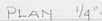
The image displays an architectural drawing that includes a plan and a section detail. The drawing is neatly organized into two main parts: Left side: There is a plan view of a structure or architectural detail at a scale of 1/4" = 1'0". Annotations and dimensions are included to describe the details and specifications required. A note at the bottom left corner reads, "FOR FURTHER DETAILS OF REFLECTORS CONSULT LIGHTCONTROLS, SHOP DRAWING S-822-6 DATED 12-7-39." This suggests that the drawing is related to an element that includes reflectors and that the document is part of a wider set of shop drawings, with a reference to another document dated December 7, 1939. Right side: You can find a section drawing marked "SECTION AA 3/8" = 1'0"" showing a vertical cut-through detail of an element. Additional annotations, dimensions, and a label for referent "REFLECTORS 25-27," provide technical information about the construction of the section illustrated. Across the bottom: There are various pieces of information which provide context for the drawings. The firm name "RITCHEY & MITCHELL REGISTERED ARCHITECTS PITTSBURGH, PENNA." is listed, indicating the office from which these plans originated. Additionally, there are notes about revisions made by individuals identified with initials, along with dates, and it mentions "walter gropius & marcel breuer associated architects, cambridge, mass." signifying their association with the project and providing a geographical reference. The title "FRANK HOUSE Pgh, PA." identifies the project's name and location, and the drawing also includes a plot plan. There is a section to the far right with a "28" encircled, likely a sheet number or mark indicating its sequence in a set of drawings. The overall appearance suggests that this is an architectural drawing related to a historical project, given the date notation from the year 1940, and involves important figures in the field of architecture, such as Walter Gropius and Marcel Breuer.
Created by gpt-4o-2024-05-13 on 2025-03-05
The image displays an architectural plan and section drawing. The drawing appears to be technical and is likely part of a set of construction or design documents. A notable feature in the image is the rectangular block in the lower right corner detailing the project information: - The architectural firm involved: "Walter Gropius & Marcel Breuer, associated architects, Cambridge, Mass," indicating that the design is associated with these prominent architects. - Another architectural firm mentioned: "Ritchey & Mitchell, registered architects, Pittsburgh, Penna." - Project information: "Drawn by: E Kennedy," and details about the specific drawing revision including the date of June 7, 1939, the project name "Frank House," and location information. The drawing number is noted as "218." The plan view shows a space labeled as "1/4" = 1' - 0"," indicating the scale of the drawing in relation to real-world measurements. It includes elements labeled "A" and "B" and is cross-referenced with "Section A-A." The section drawing on the right side shows a vertical cut through a part of the structure, detailing specific architectural elements like a wall, soffit, and a reflector labeled "25-27." Measurements and annotations explain dimensions and relationships between different construction elements. The section is also to scale, shown as "3/4" = 1' - 0." A note on the drawing suggests consulting another drawing for further details: "For further detail of reflectors consult Lightcontrol's shop drawing S-8226, dated 12-7-39." Overall, the drawing functions as part of a detailed architectural plan providing necessary information for construction or further design development.
Anthropic Claude
Created by claude-3-haiku-20240307 on 2024-12-29
The image appears to be an architectural drawing or blueprint. It contains a plan view and a section view of a structure, with various measurements and notes. The plan view shows the layout of the structure, while the section view provides a cross-sectional view. The drawing is labeled "PLAN 1/4" = 1'-0" and "SECTION A-A 3/8" = 1'-0", indicating the scale of the drawings. The drawing also includes the names of the architects, "RITCHEY & MITCHELL," and some additional notes and information.
Created by claude-3-opus-20240229 on 2024-12-29
The image shows an architectural drawing or blueprint. It is titled "Plan 'A' - 1'-0"" and has "Ritchey & Mitchell, Registered Architects, Pittsburgh, Pa." printed at the bottom, indicating they created this drawing. The plan view shows the layout and dimensions of what appears to be a small structure, possibly a house or building section. Dimensions are provided, along with details on the bottom right specifying "Walter Gropius & Marcel Breuer, associated architects, cambridge, mass." as well as "Frank House" and some additional project information. The drawing style uses thin lines and text to depict the floor plan, utilizing standard architectural drafting techniques and notation common in such technical drawings and blueprints used for construction.
Created by claude-3-5-sonnet-20241022 on 2024-12-29
This is an architectural drawing/blueprint that appears to be created by Walter Gropius & Marcel Breuer, Associated Architects from Cambridge, Massachusetts. The drawing shows both a plan view and a section view (marked as Section A-A) of what seems to be a reflector detail for the Frank House in Pittsburgh, PA. The plan is drawn at a scale of 1/4"=1'-0", while the section is at 3"=1'-0". There's a note referencing additional details about reflectors that can be found in another drawing (S-862-0) dated 10.7.39. The drawing also includes a stamp from "Ritchey & Mitchell, Registered Engineers" from Pittsburgh, Pennsylvania. There's a standard notation that "the contractor must verify all dimensions on the job and report any discrepancies to the architects."
Meta Llama
Created by us.meta.llama3-2-11b-instruct-v1:0 on 2025-03-11
The image is a technical drawing of a room, specifically the floor plan and section of a building. The drawing is hand-drawn on white paper and includes various details such as dimensions, labels, and notes. * **Floor Plan:** * The floor plan shows the layout of the room, including the location of walls, doors, windows, and other features. * The room appears to be a small, rectangular space with a door on one side and a window on the opposite side. * There are several labels and notes throughout the drawing, including "PLAN" and "SECTION AA". * **Section AA:** * The section AA drawing shows a cross-section of the room, highlighting the relationship between different levels and features. * The section appears to be looking down from the ceiling, showing the floor, walls, and ceiling in detail. * There are several labels and notes throughout the drawing, including "REFLECTORS" and "BOTTOM OF SOFFIT". * **Labels and Notes:** * The drawing includes several labels and notes that provide additional information about the room and its features. * Some of the labels include "RITCHEY & MITCHELL REGISTERED ARCHITECTS PITTSBURGH, PENNA." and "walter gropius & marcel breuer associated architects. cambridge, mass." * The notes appear to be comments or instructions from the architect or designer, providing additional context or clarification about the drawing. * **Dimensions:** * The drawing includes several dimensions, which provide measurements of the room and its features. * The dimensions are written in inches and appear to be precise measurements of the room's size and layout. * **Overall:** * The drawing appears to be a detailed and accurate representation of the room's layout and features. * The use of labels, notes, and dimensions provides a clear understanding of the room's design and construction.
Created by us.meta.llama3-2-90b-instruct-v1:0 on 2025-03-11
This image depicts a technical drawing of a building's architectural design, specifically focusing on the layout and dimensions of a room. The drawing is presented in black and white, with various symbols, notations, and measurements scattered throughout. In the top-left corner, a detailed section of the room is illustrated, showcasing the placement of doors, windows, and other features. A notation at the bottom of this section reads "PLAN 1/4" = 1'-0"" and "FOR FURTHER DETAILS OF REFLECTORS CONSULT LIGHT CONTROL'S SHOP DRAWING 3-822-6 DATED 12.7.39." This suggests that the drawing is part of a larger project, and additional information can be found in the referenced shop drawing. Adjacent to this section is another illustration, labeled "SECTION AA 3"-1'-0"" and featuring a cross-section of the room. This view provides insight into the room's vertical dimensions and layout. At the bottom of the page, a rectangular box contains the text "RITCHEY & MITCHELL REGISTERED ARCHITECTS PITTSBURGH, PENNA." This indicates that the architectural firm responsible for the design is Ritchey & Mitchell, based in Pittsburgh, Pennsylvania. Below this box, another rectangular box displays the text "revisions: walter gropius & marcel breuer associated architects, cambridge, mass." This suggests that the original design was created by Walter Gropius and Marcel Breuer, but revisions were made by Ritchey & Mitchell. The background of the image is a plain white sheet of paper, providing a clean and neutral backdrop for the technical drawing. Overall, this image presents a detailed and informative representation of a building's architectural design, highlighting the attention to detail and precision required in this field.
Amazon Nova
Created by amazon.nova-lite-v1:0 on 2025-01-10
The image appears to be an architectural drawing or blueprint. Here is a detailed description of the image: The image shows a technical drawing of a building or structure, likely a house or residential building. The drawing is labeled as a "plan" and includes dimensions and measurements. The drawing is divided into two main sections: 1. The upper section shows a floor plan or layout of the building, with various rooms and spaces labeled. There are also notes and annotations indicating dimensions, room names, and other details. 2. The lower section includes a section view or cross-section of the building, showing the vertical structure and layout of the floors and walls. The drawing is labeled with the name "Walter Gropius & Marcel Breuer," indicating that these two architects were associated with the design of this building. The location is noted as Cambridge, Massachusetts. The drawing also includes revision notes and dates, indicating that the design has undergone changes and updates over time. The latest revision date is listed as July 17, 1940. The image appears to be a technical document used for construction or design purposes, providing detailed information about the building's layout, dimensions, and construction details.
Created by amazon.nova-pro-v1:0 on 2025-01-10
The image shows a floor plan of a building with dimensions and labels. The plan is titled "Plan 14'-10" and "Section A 8'-10" and includes details such as "Reflectors 23'-27" and "Edition of Support." The drawing also includes a note that reads "For further detail of reflectors, consult Lightcontrol's Shop Drawing S-822-6." The drawing is dated December 7, 1989, and is signed by an architect. The plan appears to be a detailed blueprint of a building's floor layout, including the placement of fixtures and equipment.
Text analysis
Amazon