Machine Generated Data
Tags
Color Analysis
Feature analysis
Amazon
| Document | 68.6% | |
Categories
Imagga
| text visuals | 100% | |
Captions
Microsoft
created on 2018-03-22
| a close up of a map | 79% | |
| close up of a map | 75.2% | |
| a close up of text on a map | 68.3% | |
OpenAI GPT
Created by gpt-4 on 2025-03-06
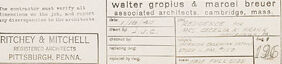
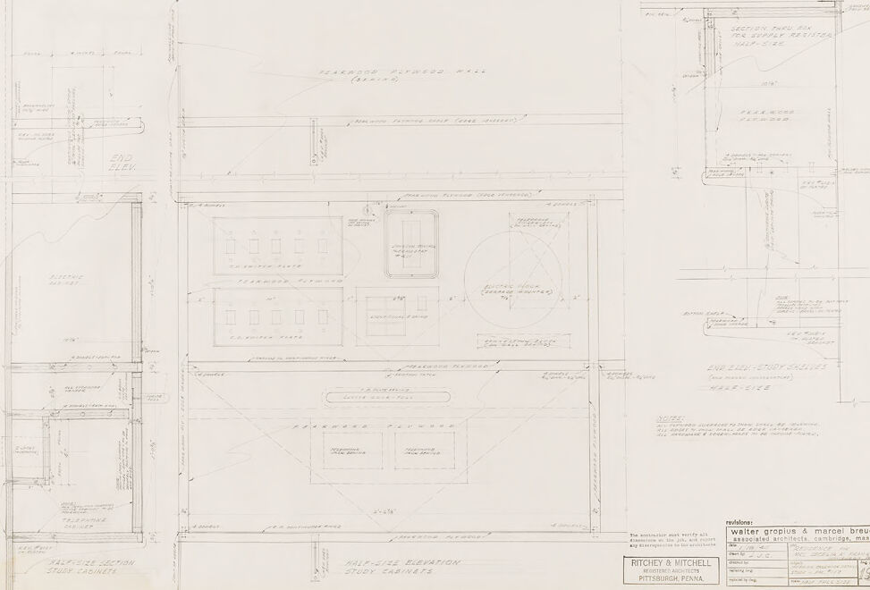
The image shows a technical drawing or architectural blueprint. The drawing features a variety of detailed plans and elevations. It appears to include sections for a building or a piece of furniture, with different views provided for clarity on the construction or design. There are annotations and dimensions noted throughout the drawing, providing specific measurements and guidance for the builder or craftsman. The drawing is likely created by an architect or a designer as part of the process for construction or manufacturing. The fine lines, symbols, and text are typical of technical drawings and schematics used in various engineering and architectural disciplines. On the bottom right, there's a stamp or label that seems to include the names of prominent architects Walter Gropius & Marcel Breuer, a project number, an address in Cambridge, Mass., and an indication that the drawing is associated with the firm Ritchey & Mitchell in Pittsburgh, Penna, which suggests that this drawing is connected to a professionally commissioned project.
Created by gpt-4o-2024-05-13 on 2025-03-06
This image is a detailed architectural drawing or blueprint consisting of multiple sections and views related to a building or a specific part of a structure. The drawing contains precise measurements, annotations, and delineations of various elements. Key components of the drawing include: 1. Multiple elevation views: Both side elevations and sectional elevations are detailed, which show the vertical elements and exterior appearances from different perspectives. 2. Floor plans: These plans outline the layout of different floors, displaying the placement of rooms, windows, and doors. 3. Detailed dimensions: Clear, exact measurements are provided for various parts of the structure, ensuring accuracy in construction. 4. Annotations and notes: Text annotations and notes provide additional information on materials, dimensions, and specific construction details. 5. Title Block: The bottom right corner contains a title block that includes the names "Walter Gropius & Marcel Breuer," who are renowned architects, indicating these individuals' involvement. It also includes the details of "Ritchey & Mitchell" from Pittsburgh, Pa., who are associated architects. 6. Sections and details: The drawing includes cross-sectional views (cut-through views) and detailed sketches to clarify construction methodologies and material use. Overall, the drawing is a technical representation used by architects and builders to guide the construction of a building, ensuring precision and compliance with design specifications.
Anthropic Claude
Created by claude-3-haiku-20240307 on 2024-12-31
The image appears to be an architectural or engineering drawing or blueprint. It contains various technical diagrams, measurements, and annotations, suggesting it is a detailed schematic or plan for some kind of structure or system. The drawing seems to be focused on technical details and specifications rather than depicting any human subjects or scenes.
Created by claude-3-opus-20240229 on 2024-12-31
The image shows an architectural blueprint or plan for what appears to be a house or residential building called the "Walter Graham & Marion Brauer" residence, designed by Ritchey & Mitchell architects in Pittsburgh, Pennsylvania. The blueprint contains detailed floor plans showing the layout and dimensions of various rooms and spaces within the structure, along with technical annotations and specifications. The plans are drawn with thin lines on a light background, giving the characteristic look of an architectural drawing or blueprint.
Created by claude-3-5-sonnet-20241022 on 2024-12-31
This appears to be an architectural drawing or blueprint showing various elevations and sections of a building project. The drawing contains multiple detailed views including what seem to be front and side elevations along with some section details. It's done in a technical drafting style with thin lines and dimensions marked throughout. The drawing bears what appears to be an architectural firm's name at the bottom - Ritchey & Mitchell from Pittsburgh, Pennsylvania. The drawing style suggests this is likely from a professional architectural or engineering office, showing construction or renovation plans for a building project. The overall layout is typical of architectural documentation, with different views arranged on the sheet to show various aspects of the structure.
Meta Llama
Created by us.meta.llama3-2-11b-instruct-v1:0 on 2025-03-13
The image presents a detailed architectural drawing of a building, showcasing its layout and design. The drawing is rendered in black ink on white paper, with various lines, shapes, and text used to convey the building's features. **Key Features:** * **Building Layout:** The drawing depicts a multi-story building with a rectangular shape, featuring several rooms and corridors. * **Room Dimensions:** Each room is labeled with its dimensions, providing a clear understanding of the building's layout and spatial relationships. * **Door and Window Locations:** The drawing indicates the locations of doors and windows, allowing for a visual representation of the building's entrances and exits. * **Text and Labels:** The drawing includes various text and labels, such as "RITCHIEY & MITCHELL" and "PITTSBURGH PENNA," which provide context and identify the architects responsible for the design. * **Scale and Proportions:** The drawing includes a scale and proportions, ensuring that the building's dimensions are accurately represented. **Overall Impression:** The drawing provides a comprehensive and detailed representation of the building's design, making it an essential tool for architects, engineers, and builders. The level of detail and precision evident in the drawing suggests that it was created for a specific purpose, such as a construction project or a design proposal.
Created by us.meta.llama3-2-90b-instruct-v1:0 on 2025-03-13
The image presents a detailed architectural blueprint, showcasing the intricate design and layout of a building or structure. The blueprint is rendered in black ink on a white background, with various lines, symbols, and notations that provide valuable information about the project. **Key Features:** * **Title Block:** Located at the bottom right corner, the title block contains essential details such as the project name, architect's name, and location. * **Floor Plan:** The central section of the blueprint depicts the floor plan, featuring rooms, corridors, and other architectural elements. * **Elevations:** The left and right sides of the blueprint display elevations, which show the exterior views of the building from different angles. * **Sections:** The top and bottom sections of the blueprint illustrate cross-sections, providing a detailed view of the building's internal structure. * **Notations and Symbols:** Throughout the blueprint, various notations and symbols are used to convey important information, such as room labels, door and window locations, and construction materials. **Overall Impression:** The blueprint appears to be a comprehensive and detailed design document, likely created for a specific construction project. The level of detail and precision suggests that it was prepared by a professional architect or engineer. The image provides a valuable insight into the design process and the careful planning that goes into creating a building or structure.
Amazon Nova
Created by amazon.nova-lite-v1:0 on 2025-02-25
The image is a detailed architectural drawing, likely a floor plan or elevation view, featuring various sections and annotations. The drawing is divided into multiple panels, each containing different types of information. The top left panel shows a half-size section labeled "STUDY CABINETS," indicating a detailed view of the study cabinets. The top right panel contains a half-size elevation labeled "STUDY CABINETS," providing a vertical view of the cabinets. The bottom left panel is another half-size section labeled "STUDY CABINETS," showing additional details. The bottom right panel has a section labeled "REV 1996," which could indicate a revision date or a specific version of the drawing. The drawing is signed by "WALTER GROPIUS & MARCEL BREUWER," suggesting the involvement of these architects in the design. The drawing also includes various measurements, dimensions, and annotations in the text, providing detailed specifications for the cabinets and their placement.
Created by amazon.nova-pro-v1:0 on 2025-02-25
The image is a technical drawing of a building, likely an architectural plan. It contains multiple sections and elevations, each detailing different aspects of the structure. The drawing is composed of several parts: a floor plan, elevations, and sections. The floor plan is central and shows the layout of a room with dimensions and annotations. There are several rectangular shapes that represent different rooms or spaces within the building. The plan includes measurements and labels for various elements, such as doors, windows, and possibly furniture or fixtures. The elevations are positioned around the floor plan. They provide a vertical view of the building's exterior and interior walls. These elevations show the height and placement of windows, doors, and other architectural features. There are annotations indicating the materials, dimensions, and other specifications. The sections are vertical cuts through the building, showing the internal structure and detailing. These sections provide insights into the construction methods and the arrangement of spaces within the building. They include measurements and labels for various elements, such as walls, floors, and ceilings. The drawing also includes a title block at the bottom right corner, which contains information about the project, such as the name of the architect, the date, and the project title. There are also revision notes and a legend explaining the symbols and abbreviations used in the drawing. Overall, the image is a comprehensive architectural plan that provides detailed information about the design and construction of a building. It is a valuable tool for architects, engineers, and contractors to understand the project's requirements and specifications.
Text analysis
Amazon