Machine Generated Data
Tags
Color Analysis
Feature analysis
Amazon
Clarifai

AWS Rekognition
| Document | 80.3% | |

Categories
Imagga
created on 2018-03-22
| text visuals | 100% | |
Captions
Microsoft
created by unknown on 2018-03-22
| a close up of text on a white background | 77.4% | |
| a close up of text on a black background | 71.7% | |
| a close up of text on a white surface | 71.6% | |
Clarifai
No captions written
Salesforce
Created by general-english-image-caption-blip-2 on 2025-06-28
a drawing of a kitchen and bathroom with plans
Created by general-english-image-caption-blip on 2025-05-04
a photograph of a drawing of a plan for a house
OpenAI GPT
Created by gpt-4 on 2025-03-08
The image you've provided is a photograph of an architectural drawing or blueprint. The drawing contains various plans, sections, and details of building elements, such as door jambs, closets, and possibly some furniture components. Text annotations and measurements are included throughout, indicating specific dimensions and materials. The drawing style is technical and precise, showing multiple views of the components to guide construction or manufacturing.
On the bottom left corner, there is a title block with the name of the firm "Ritchey & Mitchell" from Pittsburgh, Pennsylvania. The drawing suggests it may be part of a larger set of construction documents, given there is reference to sheet numbers, revisions, and a date marked clearly on the title block. It looks professionally drafted, typically used by architects, engineers, and contractors for the purpose of constructing or remodeling parts of a building.
Created by gpt-4o-2024-05-13 on 2025-03-08
This image is a technical architectural drawing that appears to be detailed plans for various sections of a closet and door jamb for a building. The drawing includes:
- Detailed views: These views show close-up details of particular sections and elements such as shelving supports, door frames, and closet interiors.
- Sections: Several section drawings (labeled D, E, B, and C) illustrate the internal structure and elements of the closet and door jamb from different angles and cross-sections.
- Elevations: Elevation drawings (labeled as Elevation A) provide a straight-on view of the door jamb and closet, showing their vertical dimensions and features.
- Plan views: Plan views show the layout from above, detailing the arrangement of the closet in relation to surrounding structures.
- Labels and measurements: The drawing is annotated with labels, dimensions, and notes specifying materials, construction methods, and functional details such as shelving support and panel type.
At the bottom right, the architectural firm names "Ritchey & Mitchell, Pittsburgh, Penna." and "Walter Gropius & Marcel Breuer, Associated Architects, Cambridge, Mass." are indicated, along with additional notes about revisions and drawing scale.
Anthropic Claude
Created by us.anthropic.claude-3-5-sonnet-20241022-v2:0 on 2025-06-25
This image appears to be an architectural drawing or blueprint showing various technical details and specifications. It includes multiple views and cross-sections of what appears to be interior details, possibly for a closet or storage space. The drawings show elevations, sections, and detailed measurements, with labels like "Section B," "Section C," and "Elevation A." At the bottom of the drawing is a title block identifying it as work by Walter Gropius & Marcel Breuer, with "Ritchey & Mitchell" of Pittsburgh, Pennsylvania also noted. The drawing includes detailed construction specifications and dimensions, rendered in a professional architectural drafting style typical of mid-century architectural documentation.
Created by claude-3-haiku-20240307 on 2024-12-31
This image appears to be an architectural drawing or technical diagram. It contains multiple sketches and diagrams of various design elements, including elevations, sections, and details. The drawings seem to be related to the design of a building or structure, with annotations and labels providing additional information. While the image does not contain any human faces, it provides a detailed technical illustration of the structural components and design specifications.
Created by claude-3-opus-20240229 on 2024-12-31
The image shows an architectural blueprint or plan view drawing of what appears to be a residential structure, likely a house. The blueprint contains detailed floor plans for multiple sections labeled as "Detail Y", "Section A", "Section B", and "Section C". Various rooms and spaces are delineated, including a living room, kitchen, bedrooms, bathrooms, closets, and a porch or exterior space. Measurements and dimensions are provided throughout the plans. The blueprint also has a title block in the bottom right corner identifying the architects as "Walter Gropius & Marcel Breuer" and the structure as a "Ditchey & Mitchell Residence, Pittsburgh, Penna."
Created by claude-3-5-sonnet-20241022 on 2024-12-31
This is an architectural drawing or blueprint showing various technical details and plans. The image includes multiple views - floor plans, elevations, and sections - of what appears to be interior architectural elements, possibly for closets or built-in furniture pieces. The drawing is labeled with numbers and measurements, and includes details marked as "Section A," "Section B," "Section C," and "Elevation A." At the bottom of the drawing, there's a title block identifying it as work by "Walter Gropius & Marcel Breuer" and appears to be for "Ritchey & Mitchell" in Pittsburgh, Pennsylvania. The drawing contains various construction details with annotations and dimensions, all rendered in a professional architectural drafting style typical of mid-20th century technical drawings.
Meta Llama
Created by us.meta.llama3-2-11b-instruct-v1:0 on 2025-03-15
The image presents a detailed architectural drawing of a building, showcasing various rooms and their corresponding dimensions. The drawing is rendered in black ink on white paper, with precise measurements and annotations providing a comprehensive overview of the structure's layout.
Key Features:
- Scale: The drawing is scaled at 1/4 inch = 1 foot, allowing for accurate measurements and calculations.
- Rooms: The building features several rooms, including a living room, kitchen, dining room, bedrooms, and bathrooms. Each room is labeled and accompanied by its dimensions, providing a clear understanding of the space.
- Doors and Windows: Doors and windows are also depicted, with their locations and sizes clearly marked. This information is crucial for determining the flow of natural light and the overall functionality of the building.
- Furniture and Fixtures: Some furniture and fixtures are included in the drawing, such as a fireplace, bookshelves, and a closet. These details add to the overall sense of realism and help to visualize the completed space.
- Annotations: The drawing includes various annotations, including notes on the materials used, the location of electrical outlets, and other relevant information. These annotations provide additional context and help to clarify any ambiguities in the drawing.
- Signatures: The drawing bears the signatures of Walter Gropius and Marcel Breuer, two renowned architects who were associated with the Cambridge, Mass. office of Walter Gropius and Associates. This adds to the credibility and authenticity of the drawing.
Conclusion:
The architectural drawing presented in the image is a meticulous and detailed representation of a building's layout. The inclusion of precise measurements, annotations, and signatures from renowned architects makes this drawing a valuable resource for architects, builders, and anyone interested in understanding the intricacies of building design.
Created by us.meta.llama3-2-90b-instruct-v1:0 on 2025-03-15
The image presents a detailed architectural drawing, likely created for a residential or commercial building project. The drawing is divided into several sections, each providing specific information about the building's design and layout.
Key Features:
- Sectional Views: The drawing includes multiple sectional views of the building, showcasing its interior and exterior features. These views provide a comprehensive understanding of the building's structure and layout.
- Elevation Drawings: Elevation drawings are also included, offering a detailed representation of the building's exterior facades. These drawings highlight the building's architectural style, materials, and design elements.
- Floor Plan: A floor plan is visible, illustrating the building's internal layout and room configurations. This plan helps to visualize the flow of spaces and the relationships between different areas of the building.
- Annotations and Labels: Throughout the drawing, annotations and labels provide additional context and clarify specific design elements. These notes may include information about materials, dimensions, and construction details.
- Architectural Firm Information: The drawing includes the name and contact information of the architectural firm responsible for the design, along with other relevant details such as the project number and date.
Overall Impression:
The image suggests that the architectural firm has carefully considered every aspect of the building's design, from its overall layout to the smallest details. The level of detail and precision in the drawing indicates a high level of professionalism and attention to detail.
Amazon Nova
Created by amazon.nova-lite-v1:0 on 2025-01-13
The image shows a detailed architectural drawing of a house, likely a floor plan or elevation. The drawing is labeled with various sections and details, including "Elevation A," "Sections B," and "Section C." The drawing also includes measurements and annotations, such as "Scale 1/4" = 1'-0"" and "Elevation A." The drawing appears to be a technical drawing created by an architect or engineer, and it is likely used for construction or design purposes.
Created by amazon.nova-pro-v1:0 on 2025-01-13
The image shows a technical drawing of a building, with different sections and elevations of the structure. The drawing is on a white background, and it includes various details such as dimensions, materials, and construction methods. The drawing appears to be a blueprint or architectural plan, with different sections and elevations of the building shown in separate panels. The drawing includes annotations and labels, indicating the different parts of the building and their functions. The overall design of the building appears to be modern and functional, with a focus on efficiency and practicality.
Google Gemini
Created by gemini-2.0-flash on 2025-05-04
Here is a description of the image:
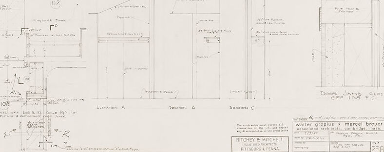
The image is a scan of an architectural drawing, rendered in pencil or similar medium. It's composed of various detailed diagrams and notes pertaining to the design and construction of a closet and related architectural elements. The drawing shows detailed cross-sections, elevations, and plan views. There are annotations providing measurements, material specifications, and construction details. Key areas of focus include the door jamb of the closet, the arrangement of shelves, and various structural components. At the bottom right, there's a section that provides information about the architectural firm responsible for the design, which is credited to Walter Gropius & Marcel Breuer, and it appears to be filed by Ritchey & Mitchell. The document seems to be historical, dating back to around 1940, based on the date and revision notes.
Created by gemini-2.0-flash-lite on 2025-05-04
This image appears to be a detailed architectural drawing, likely a blueprint or a technical sketch. It features multiple views, sections, and details of a closet, providing instructions for its construction. Here's a breakdown:
- Layout: The image is densely packed with various drawings. At the top are details and sections. The left side contains a floor plan, with details and sections further down.
- Content: The drawing focuses on a closet design. The detailed sections (labelled "SECTION B", "SECTION C", etc.) show the internal structure, including walls, shelves, the door frame, and potentially the ceiling. "DETAIL Y F.S." and "PLAN" give a closer look at specific components. The annotation "Door Jamb Closet OFF 108 F.S." suggests the design is for a door jamb for a closet.
- Annotations: The drawing is covered in handwritten notes, measurements, and labels. These details indicate materials (e.g., "pine painted"), dimensions, and specific construction instructions. Phrases like "shelves, etc." and "typical intersection of shelves" give information about how things fit together.
- Professional Context: The bottom right features a title block with information about the architects (Walter Gropius & Marcel Breuer), the project location (Cambridge, Mass.), and date. The firm Ritchey & Mitchell, Registered Architects, is also indicated.
In short, the image is a professional architectural drawing documenting the design and construction details of a closet. It's a snapshot of the design process, demonstrating how different views and annotations are used to convey complex information.
Mistral Pixtral
Created by us.mistral.pixtral-large-2502-v1:0 on 2025-05-31
The image is an architectural drawing, likely a detailed plan for a specific part of a building, such as a room or a section of a building. Here is a breakdown of the various elements in the drawing:
Sections and Elevations:
- The drawing includes multiple sections and elevations, which are different views of the structure. These views help in understanding the vertical and horizontal dimensions and layout of the space.
- Elevation A shows a front view of a wall with a door and possibly a window or opening.
- Sections B, C, D, and E provide cross-sectional views at different points, showing the internal structure, including walls, ceilings, and floor details.
Details:
- Detail Y and Detail X are zoomed-in views of specific parts of the structure, providing more precise measurements and construction details.
- These details might include information about the construction of doors, windows, or other architectural elements.
Annotations:
- The drawing includes various annotations and dimensions, which are critical for construction. These annotations specify measurements, materials, and other important details.
- For example, there are notes about the placement of doors, the thickness of walls, and the height of ceilings.
Plans:
- The plan view (Plan on Ceiling at 108'-8") shows the layout from above, indicating the position of walls, doors, and other features.
- This view helps in understanding the spatial arrangement and flow of the space.
Revisions:
- There is a revision note at the bottom right, indicating changes or updates to the original plan. This is common in architectural drawings to ensure that the latest design is being used.
Architectural Firms:
- The drawing is credited to two architectural firms: "TROPIUS & MARCEL BREUER ASSOCIATED ARCHITECTS" and "MITCHEY & MITCHELL MECHANICAL ENGINEERS."
- This suggests that the project involved collaboration between different professionals.
Date and Location:
- The drawing is dated March 23, 1957, and the location mentioned is Cambridge, Massachusetts.
- This provides context about when and where the project was designed.
Overall, the drawing is a comprehensive set of plans and details for a specific architectural project, providing all necessary information for construction and implementation.
Qwen
Created by Qwen/Qwen2.5-VL-7B-Instruct on 2025-07-20
The image appears to be an architectural drawing, specifically a set of detailed plans and sections for a closet and adjacent areas. The drawing includes:
- Detail Y, F.S.: This is a detailed elevation view of a section, possibly showing the framing and construction details of a closet.
- Section D and E: These sections likely illustrate the interior construction of the closet, showing the support structures, shelves, and door frames.
- Section C: This section appears to be a vertical cut through the closet, showing the depth and details of the construction.
- Elevation A: This view shows the front elevation of the closet and adjacent areas, including door details and the spatial relationship between the closet and the main room.
- Plans of Closets Off 108 & 112: These plans show the layout and dimensions of the closets located off spaces 108 and 112.
- Perspective Floor Plan: This likely shows the layout of the floor, including the placement of the closets and the areas they are located in.
- Door Jamb Closet Off 108 F.S.: This detail focuses on the construction of the door jamb for a closet located off space 108.
The drawing is labeled with dimensions and notations that provide precise measurements and construction details. It is signed by Walter Gropius and Marcel Breuer, along with the firm Ritechey & Mitchell, suggesting it is from the Bauhaus era or influenced by the functionalist architectural style. The document appears to be a part of a larger architectural project, possibly related to the design of a building or a specific interior space.
Created by Qwen/Qwen2.5-VL-72B-Instruct on 2025-07-20
This image is a detailed architectural blueprint or construction drawing, likely for a built-in closet or storage unit. It includes multiple views and sections of the structure:
- Detail Y F.S.: This section shows a close-up view of a part of the structure, possibly a joint or a specific component, with annotations and dimensions.
- Sections D and E: These sections provide cross-sectional views of the structure, showing internal components and how different parts are assembled.
- Elevation A: This is a front view of the structure, showing the overall shape and arrangement of the shelves and other components.
- Sections B and C: These sections provide additional cross-sectional views, possibly from different angles or focusing on different parts of the structure.
- Door Jamb Closet Off 108 F.S.: This section shows the details of the door jamb and the closet, including the door and its hinges.
- Plywood Drawers: The drawing includes details of plywood drawers, showing their construction and how they fit into the overall structure.
- Annotations and Dimensions: Throughout the drawing, there are numerous annotations and dimensions, indicating the sizes and specifications of various parts of the structure.
The drawing is signed by Walter Gropius and Marcel Breuer, with Ritchey & Mitchell as the registered architects from Pittsburgh, Pennsylvania. The drawing number is 258.
Text analysis
Amazon