
Machine Generated Data
Tags
Color Analysis
Feature analysis
Amazon
| Document | 86.7% | |
Categories
Imagga
| text visuals | 100% | |
Captions
Microsoft
created on 2018-03-22
| a screenshot of text | 82.9% | |
| a close up of text on a white surface | 78.1% | |
| a close up of text on a white background | 78% | |
OpenAI GPT
Created by gpt-4 on 2025-03-06
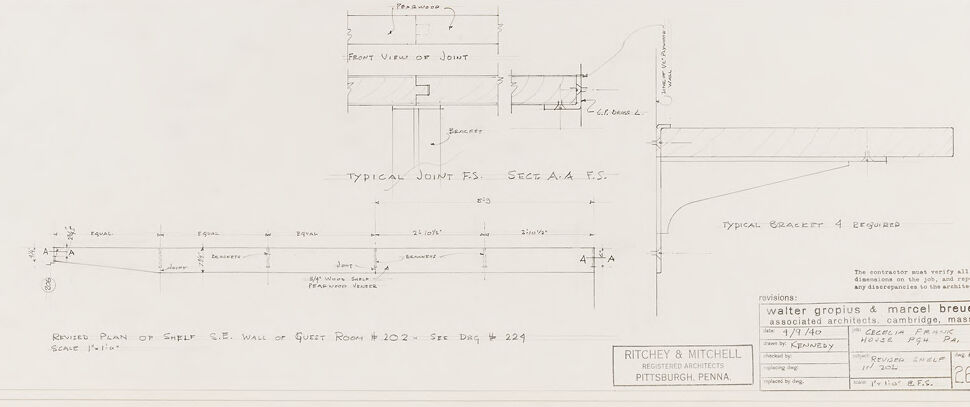
This image appears to be an architectural drawing or a technical blueprint, illustrating the plan and details of a building component. The drawing features several annotated sections with precise measurements and construction guidelines. For example, it includes a "Revised Plan of Shelf C.E. Wall of Quiet Room #202 & 224" with a scale of 1 1/2"=1'-0" indicating the scale at which the drawing was made. It includes detailed views of a "Typical Joint E.S.C. & A.S.F." or possibly "E.S.W. & A.S.F." showing specific elements such as flanges, joints, brackets, and their respective dimensions. The right side of the image shows a "Typical Bracket 4 Required" with a vertical profile and an annotated section. There are revisions noted in the bottom right corner, mentioning names, which could be the names of architects or designers involved in making the revisions to the plan. The drawing also includes the name of the firm "Ritchey & Mitchell," which is likely the architecture or engineering firm responsible for the drawing, with locations listed as Pittsburgh, Penna. (Pennsylvania), with a reference to associate architects in Cambridge, Mass. The various lines, notations, and detailed drafting style suggest that this is a professional technical document used for construction or renovation purposes.
Created by gpt-4o-2024-05-13 on 2025-03-06
This image is an architectural drawing that features detailed plans and specifications for a specific part of a building – the shelf on the southeast wall of Guest Room #202. The plan is drawn to a scale of 1½" = 1'0". Key elements in the drawing include: 1. **Elevation and Section Views:** - The "Front View of Joint" shows a detailed depiction of the joint design in the shelf structure. - "Typical Joint F.S. Sect. A.A F.S." shows a cross-sectional view of the joint, including dimensions and how the parts come together. - "Typical Bracket 4 required" includes a side view of the bracket needed for the shelf, indicating necessary support details. 2. **Plan View:** - The "Revised Plan of Shelf S.E. Wall of Guest Room #202 - See Drwg #224" provides a top-down view of the shelf's position and measurements along the southeast wall. 3. **Dimensions and Notes:** - Several sections include specific measurements and annotations about the shelf's dimensions and the distance between support brackets. Measurements are detailed to the 1/16th of an inch for precision. - "Equal" notations indicate symmetrical placement of supports/brackets. 4. **Revisions and Title Block:** - In the lower right corner, there is a title block listing the project information: Architects are Walter Gropius & Marcel Breuer, associated with Ritchey & Mitchell, Registered Architects from Pittsburgh, Pennsylvania. - The drawing is revised and dated 8/29/40 and includes scale notation and drawing number (#266). The precise, technical nature of this architectural drawing illustrates the attention to detail necessary for constructing and installing architectural elements like shelves in a building, reflecting the meticulous planning process of architects.
Anthropic Claude
Created by claude-3-haiku-20240307 on 2024-12-30
The image appears to be an architectural drawing or plan showing a typical joint and a typical bracket for a structure. The drawing provides detailed dimensions and specifications for these structural elements. There are no identifiable human figures or faces in the image.
Created by claude-3-opus-20240229 on 2024-12-30
The image shows architectural drawings and plans for a building called the Walter Gropius & Marcel Breuer Associated Architects Guest Room, Pittsburgh, Pennsylvania. It includes front and side view drawings showing the dimensions and layout of the room. The image also contains information about the project at the bottom, listing the architects Ritchey & Mitchell and their contact details in Pittsburgh.
Created by claude-3-5-sonnet-20241022 on 2024-12-30
This is an architectural drawing or technical blueprint showing various construction details. The image contains multiple views of what appears to be a joint design, including a "Front View of Joint" and a "Typical Joint F.S." The drawing includes detailed measurements and specifications, and is labeled as being for "Guest Room #102." The document was created by Walter Gropius & Marcel Breuer architects, with Ritchey & Mitchell of Pittsburgh, Pennsylvania listed as collaborators. The drawing shows precise dimensions and construction details for what appears to be a shelf or wall installation, with careful attention to joints and connections. It's drawn to scale (1/2"=1'0") and includes both plan and elevation views of the design elements.
Meta Llama
Created by us.meta.llama3-2-11b-instruct-v1:0 on 2025-03-13
The image presents a technical drawing, specifically a revised plan of a shelf, accompanied by detailed measurements and annotations. The drawing is rendered in black ink on white paper, with the text and lines providing clarity and precision. **Key Features:** * **Title:** "Revised Plan of Shelf" is written at the bottom left corner of the drawing. * **Measurements:** Various measurements are provided throughout the drawing, including the width, depth, and height of the shelf. * **Annotations:** Notes and labels are included to clarify the design and functionality of the shelf. * **Scale:** A scale is indicated at the bottom left corner of the drawing, allowing for accurate measurement and proportion. * **Signatures:** The signatures of Walter Gropius and Marcel Breuer are visible at the bottom right corner of the drawing, indicating their involvement in the design process. * **Date:** The date "1/7/40" is written at the bottom right corner of the drawing, suggesting that the revised plan was created in January 1940. * **Location:** The location "Pittsburgh, PA" is indicated at the bottom right corner of the drawing, providing context for the project's origin. **Overall Impression:** The revised plan of the shelf is a meticulous and detailed technical drawing that showcases the attention to detail and precision required in architectural design. The inclusion of measurements, annotations, and signatures adds to the drawing's authenticity and credibility, making it a valuable resource for architects, designers, and historians.
Created by us.meta.llama3-2-90b-instruct-v1:0 on 2025-03-13
The image presents a detailed architectural drawing of a shelf, accompanied by a plan of the shelf and a section view. The drawing is rendered in black ink on white paper, with the title "Revised Plan of Shelf" inscribed at the bottom left corner. The plan view of the shelf is situated at the top center of the page, while the section view is positioned below it. A detailed drawing of the joint between the shelf and the wall is also included, featuring various dimensions and annotations. In the bottom-right corner, a box contains the names "Walter Gropius & Marcel Breuer" and "Associated Architects," along with their address in Cambridge, Massachusetts. The date "1/9/40" is written above this box, indicating the creation date of the drawing. Below the box, a smaller box displays the text "Ritchey & Mitchell Registered Architects Pittsburgh, Penna." and the date "11/20/40." The background of the image is a plain white sheet of paper, providing a clean and neutral backdrop for the architectural drawing.
Amazon Nova
Created by amazon.nova-lite-v1:0 on 2025-02-25
The image appears to be a technical architectural drawing, specifically a revised plan of a shell wall of a guest room. The drawing includes dimensions, measurements, and annotations in pencil. The drawing is labeled "REVISED PLAN OF SHELL S.T. WALL OF GUEST ROOM #202 - SEE DWG #229" and is signed by "Walter Gropius & Marcel Breuer." The drawing also includes a scale of 1/2" = 1'-0" and a date of 4/1/40. The drawing is part of a collection of architectural drawings by Walter Gropius and Marcel Breuer, who were prominent architects and designers in the mid-20th century.
Created by amazon.nova-pro-v1:0 on 2025-02-25
The image appears to be a technical drawing or blueprint of a structural design. The drawing is printed on a piece of paper, and it features various lines, dimensions, and annotations. The drawing shows a detailed plan of a structural element, possibly a beam or a support structure. The drawing includes a front view, a top view, and a side view of the structure, along with detailed dimensions and measurements. The drawing also includes annotations and notes, such as "Typical Joint," "Front View of Joint," and "Typical Bracket 4 Required." The drawing is likely used by engineers, architects, or construction professionals to plan and design a specific structural component.
Text analysis
Amazon


