Machine Generated Data
Tags
Color Analysis
Feature analysis
Amazon
Clarifai

Clarifai
| Vehicle | 43.9% | |
Categories
Imagga
created on 2018-03-22
| text visuals | 99.9% | |
| paintings art | 0.1% | |
Captions
Microsoft
created by unknown on 2018-03-22
| a close up of text on a white surface | 63.2% | |
| a white sign with black text | 43.6% | |
| a close up of text on a white background | 43.5% | |
Clarifai
No captions written
Salesforce
Created by general-english-image-caption-blip-2 on 2025-06-28
a drawing of a building with several different plans
Created by general-english-image-caption-blip on 2025-05-04
a photograph of a drawing of a plan for a house
OpenAI GPT
Created by gpt-4 on 2025-03-08
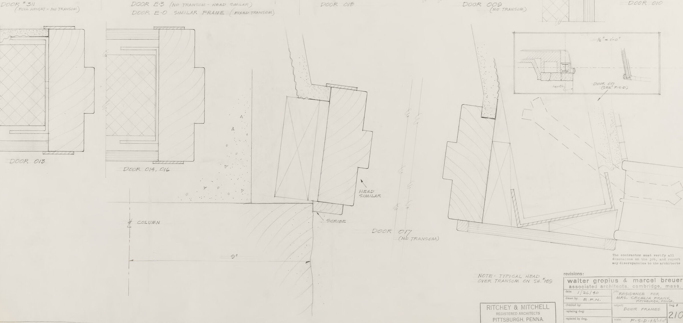
This is an architectural drawing featuring detailed sketches of door frames and a column. There are eight door frames in total, each with specific notes on dimensions and design elements, like varied thicknesses and treatments such as "two thickness – head similar" or "one thickness." In the lower left corner, there's a sketch of a column with its dimension noted as "9'."
At the bottom of the drawing is a note section that credits the creators of the plans, which include names Walter Gropius and Marcel Breuer, two influential figures in modern architecture associated with the Bauhaus movement. The project is titled "TERMINAL BUILDING, GATEWAY CENTER, PITTSBURGH, PA," and the drawing is related to "SCHEDULE OF DOORS," with a date and information about the architects' firm location in Pittsburgh, Pennsylvania.
The drawing style indicates precision and clarity, typical for architectural plans, enabling the construction of the elements as designed.
Created by gpt-4o-2024-05-13 on 2025-03-08
The image is a detailed architectural drawing focused on various door frame designs and sections. The sheet contains multiple labeled segments for different door types, indicated with labels such as Door D11, Door D05, Door D01A, and so on. Each section shows the cross-sectional details of how the door frames are to be constructed including information on the frames, thresholds, and clearances required.
In addition to the door sections, there are detailed notes and annotations specifying the features of each door design, such as "no transom" or "fixed transom." The lower right corner of the drawing includes the title block, which provides essential information about the project, including the names of the architects (Walter Gropius & Marcel Breuer), the architectural firm (Ritchey & Mitchell), and the project details such as the drawing number (210) and the date.
There is also a small detail drawing in the bottom right portion illustrating a particular structure (likely a cross-sectional detail of a door within a column or a wall intersection) further emphasizing the intricacies and measurements necessary in the construction.
The drawing is highly technical and would be used by builders and architects to ensure precise measurements and construction of the door frames as part of a larger architectural project.
Anthropic Claude
Created by us.anthropic.claude-3-5-sonnet-20241022-v2:0 on 2025-06-24
This image appears to be an architectural drawing or blueprint showing various door frame details. The drawing is labeled with door numbers (like "Door C-D", "Door C-E", etc.) and shows different door frame configurations in elevation view. The drawing is from the architectural firm Walter Gropius & Marcel Breuer for a project in Pittsburgh, Pennsylvania, as indicated in the title block at the bottom of the sheet. The drawing number appears to be 210, and it includes technical notes about frame transitions. The drawings are simple line work showing the profiles and dimensions of different door frame types, with some cross-hatching to indicate sections. It's a technical document typical of architectural construction documentation from what appears to be the mid-20th century.
Created by claude-3-haiku-20240307 on 2024-12-30
The image appears to be a technical drawing or blueprint of architectural components. It contains various sketched outlines and dimensions of different door and frame designs. The drawing seems to be part of an engineering or construction plan, likely for a building or structure. The details provided in the drawing would be used by architects, engineers, or construction workers to create the physical elements depicted in the design.
Created by claude-3-opus-20240229 on 2024-12-30
The image shows a collection of technical drawings or blueprints for some kind of architectural project. The drawings depict various views and cross-sections of rectangular structures, likely representing different parts or details of a building design. Measurements and annotations are included on the sketches. In the bottom right corner, there is a title block with project information including the architects "Ritchey & Mitchell" in Pittsburgh, Pennsylvania. The sketches are done in pencil or ink on what appears to be grid or drafting paper, giving them a precise, engineered look typical of architectural plans and elevations.
Created by claude-3-5-sonnet-20241022 on 2024-12-30
This appears to be an architectural drawing showing various door frame details and specifications. The drawing includes multiple door frame elevations labeled with numbers like "Door 201," "Door 202," etc. The plans show cross-sections and profiles of different door frames, with some noting "no transom" or "with transom." There are detailed technical drawings of the frame configurations, including hatching to indicate solid sections. The drawing is labeled as being from "Walter Gropius & Marcel Breuer" architects, and includes a title block in the bottom right corner with project information for "Ritchey & Mitchell" in Pittsburgh, Pennsylvania. It appears to be a professional architectural detail drawing used for construction purposes, with precise measurements and specifications for door installations.
Meta Llama
Created by us.meta.llama3-2-11b-instruct-v1:0 on 2025-03-15
The image presents a technical drawing of a building's floor plan, showcasing the layout and design of the structure. The drawing is rendered in pencil on a large sheet of paper, with the title "RITCHIEY & MITCHELL ASSOCIATES ARCHITECTS PITTSBURGH PENNA" prominently displayed in the bottom-left corner.
Key Features:
- Floor Plan: The drawing depicts the floor plan of the building, including various rooms, corridors, and stairwells.
- Doors and Windows: The drawing highlights the location and size of doors and windows throughout the building.
- Dimensions: The drawing includes measurements and dimensions for each room and feature, providing a detailed understanding of the building's layout.
- Labels: The drawing features labels and annotations that identify different areas of the building, such as "DOOR 1" and "ROOM 2".
- Scale: The drawing is drawn to scale, allowing for accurate measurements and calculations.
- Authorship: The drawing is attributed to Ritchiey & Mitchell Associates Architects, with the Pittsburgh, Pennsylvania office listed as the location.
Overall Impression:
The image provides a comprehensive and detailed view of the building's floor plan, making it an essential tool for architects, engineers, and builders. The drawing's clarity and precision demonstrate the attention to detail and expertise of the architects who created it.
Created by us.meta.llama3-2-90b-instruct-v1:0 on 2025-03-15
The image presents a detailed architectural drawing of a building's door and wall system, showcasing various components and their relationships. The drawing is divided into several sections, each highlighting a specific aspect of the design.
Door Frames
- The top section features six door frames, labeled "DOOR #1" to "DOOR #6," with corresponding dimensions and notes.
- Each frame is depicted in a different orientation, providing a comprehensive view of the door's design.
Wall Sections
- The bottom section illustrates two wall sections, labeled "WALL SECTION" and "WALL SECTION (ALTERNATE)," which demonstrate the door's integration into the surrounding wall.
- These sections offer a detailed look at the door's placement and relationship with the adjacent walls.
Notes and Dimensions
- Throughout the drawing, notes and dimensions are provided to clarify the design intent and ensure accurate construction.
- These annotations include information on materials, sizes, and other relevant details.
Architectural Firm
- In the bottom-right corner, the architectural firm's information is displayed, including their name, address, and project details.
- This section serves as a reference point for the project's context and ownership.
Overall, this image provides a thorough understanding of the building's door and wall system, offering valuable insights for architects, engineers, and contractors involved in the project.
Amazon Nova
Created by amazon.nova-lite-v1:0 on 2025-01-13
The image is a detailed architectural drawing of various door frames and their specifications. The drawing is divided into multiple sections, each labeled with different door types and their respective dimensions. The labels include "DOOR 011," "DOOR 012," "DOOR 013," "DOOR 014," "DOOR 015," and "DOOR 016," each with detailed notes on their design and construction. The drawing also includes a section labeled "TYPICAL HEAD EVER TRANSOM ON 5K 765," providing specifications for a typical head over a transom on a 5K 765 frame. Additionally, there is a note at the bottom of the drawing that reads "RITCHEY & MITCHELL PITTSBURGH, PENNA," indicating the firm responsible for the design and the location of the firm. The drawing is a technical blueprint, likely used for construction or renovation purposes.
Created by amazon.nova-pro-v1:0 on 2025-01-13
The image is a drawing of a door frame. The drawing is divided into multiple sections, each representing a different aspect of the door frame. The top section shows the overall layout of the door frame, while the bottom section provides a detailed view of the door frame's components. The drawing includes measurements and annotations, indicating the dimensions and materials used in the construction of the door frame. The drawing also includes a section labeled "DOOR FRAME," which shows the door frame's components in more detail. The drawing is likely used by architects or builders to plan and construct the door frame.
Google Gemini
Created by gemini-2.0-flash-lite on 2025-05-04
Here's a description of the image:
Overall Impression:
The image is a technical drawing, likely an architectural blueprint, with detailed cross-sectional views of various door designs. It appears to be a hand-drawn sketch, with annotations and labels.
Specific Elements and Annotations:
- Door Profiles: Several different door profiles are depicted in cross-section. They are labeled with designations like "DOOR 311," "DOOR E5," "DOOR O1B," "DOOR O1G" and so on.
- Detailed Annotations: Extensive annotations label the various components of the door and surrounding structure. These include descriptions like "HEAD SIMILAR," "COLUMN," "SCRIBE," and "NO TRANSOM".
- Dimensioning: Some dimensions are provided, such as the "3" x 6" o/c" and a section indicating a "9" distance.
- Material Indication: Hachures and shading suggest the use of different materials like wood, perhaps framing, and the door panels themselves.
- Architectural Information: At the bottom, there is a title block that identifies the project: "Walter Gropius & Marcel Breuer, Associated Architects, Cambridge, Mass." along with project details, drawing title "DOOR FRAMES," and a drawing number "210".
Overall Style and Purpose:
- The image has a technical, formal, and precise style.
- The intent of the drawing is to illustrate the precise construction and assembly of various door types, which would be used for construction purposes.
- The drawing would have been used by carpenters and other workers to manufacture or install the doors.
Created by gemini-2.0-flash on 2025-05-04
Here's a description of the image based on the provided information:
The image is a scan of an architectural drawing or blueprint. It appears to be a technical drawing detailing different door types or doorframe configurations. The drawing is in black and white.
Here's a breakdown of the elements visible:
- Door Details: The majority of the drawing consists of section views of different door designs, labeled with identifiers like "DOOR *311," "DOOR E.5," "DOOR O13," "DOOR CA, 016," etc. These sections show the construction details, including the door slab, frame, and potentially the surrounding wall.
- Additional Notes: The drawing includes notes like "Note - typical head over transom on sheets" suggesting it's related to other drawings in a set. Other details like "Column" and "Scribe" are also labeled.
- Architect Information: In the lower right corner, there's information identifying the architects as "Walter Gropius & Marcel Breuer, Associated Architects, Cambridge, Mass." Below this is the firm "RITCHEY & MITCHELL REGISTERED ARCHITECTS PITTSBURGH PENNA."
- Revisions and Project Information: The drawing also includes information about revisions, drawn by, checked by, and other project details in a formatted box.
- Technical Drawing Style: The overall style is that of a technical drawing, with precise lines, annotations, and labels, all in monochrome.
In essence, the image is a documented and detailed architectural plan focused on door design and construction.
Mistral Pixtral
Created by us.mistral.pixtral-large-2502-v1:0 on 2025-05-30
The image is an architectural drawing that appears to be a detailed technical plan of various door frames and their transoms. The drawing includes multiple elevation views of different door types, each labeled with specific designations such as "DOOR 01," "DOOR 02," "DOOR 03," etc. These labels indicate different door configurations and their corresponding transoms or frames.
Key elements in the drawing include:
Door Designations: Each door is labeled with a unique identifier (e.g., DOOR 01, DOOR 02) and additional notes such as "ON TRANSOM," "METAL DOOR," or "SIMILAR FRAME."
Elevation Views: The drawing provides front elevation views of the doors, showing the dimensions and details of the door frames, transoms, and surrounding structures.
Dimensions and Measurements: The drawing includes precise measurements and dimensions for each door and its components, ensuring accurate construction and installation.
Annotations: There are various annotations and notes scattered throughout the drawing, providing additional information about the materials, construction methods, and specific details of each door.
Architectural Firm Information: At the bottom of the drawing, there is information about the architectural firm responsible for the design. The firm is identified as "RITCHEY & MITCHELL" based in Pittsburgh, Pennsylvania. Additional details include the names of the architects, Walter Gropius and Marcel Breuer, and the date of the drawing.
Drawing Number and Scale: The drawing is numbered "2/0" and includes a scale for reference, ensuring that the dimensions can be accurately interpreted.
Overall, the drawing is a comprehensive technical document used in the construction process to ensure that the doors and their frames are built according to the specified designs and dimensions.
Qwen
Created by Qwen/Qwen2.5-VL-7B-Instruct on 2025-07-20
The image is a technical drawing that appears to be a set of architectural or construction plans, specifically for "Door Frames." It is a detailed sketch featuring various door frame designs with annotations providing specific names and descriptions for each door frame. The drawings are labeled with codes such as "DOOR *311," "DOOR E:3," "DOOR E:0," "DOOR 018," "DOOR 009," and "DOOR 010." Each drawing is accompanied by a description, such as noting the presence or absence of a transom and the type of frame.
The bottom portion of the drawing includes a scale, a note about typical head over transom, and a reference to an earlier sheet (SH. 169). The drawings are signed and dated, indicating they were created on January 26, 1940, by an architect or engineer named E.F.N. The bottom of the page also contains information about the project, including the architects' names, Walter Gropius and Marcel Breuer, and the client, Mrs. Cecelia Frank in Pittsburgh, Pennsylvania. It specifies that the drawings are related to the replacement of a dwelling and includes a reference to "F.S.D." and "210," which might be related to the project or drawing set number.
Created by Qwen/Qwen2.5-VL-72B-Instruct on 2025-07-20
This image is a detailed architectural drawing titled "Door Frames," created by Walter Gropius and Marcel Breuer, associated architects from Cambridge, Massachusetts, for a residence for Mrs. Cecelia Frank in Pittsburgh, Pennsylvania. The drawing is dated 1/26/40 and is drawn to a scale of 1/2"=1'-0". The drawing is prepared by Ritchey & Mitchell, registered architects from Pittsburgh, Pennsylvania.
The drawing shows various door frames with detailed cross-sections and notes. Each door frame is labeled with a specific door number, such as "DOOR 010," "DOOR 011," "DOOR E3," etc. The details include:
- Full-height doors without transoms.
- Doors with similar frames and fixed transoms.
- Notes on the typical head over the transom.
- Specifications for the head and scribe.
- A column is also shown with an elevation view.
The drawing includes annotations and notes for the contractor to verify all dimensions on the job and report any discrepancies to the architects. There is also a small inset detail showing a specific door frame with a hearth and the door labeled "DOOR 017 (SEE F.S.D.)." The overall layout is organized, with each door frame clearly labeled and detailed.
Text analysis
Amazon