
Machine Generated Data
Tags
Color Analysis
Feature analysis
Amazon
| Document | 69% | |
Categories
Imagga
| text visuals | 100% | |
Captions
Microsoft
created by unknown on 2018-03-22
| a close up of text on a whiteboard | 81.2% | |
| a close up of a whiteboard | 78.7% | |
| close up of text on a whiteboard | 78.6% | |
Clarifai
created by general-english-image-caption-blip on 2025-05-11
| a photograph of a drawing of a plan for a house | -100% | |
OpenAI GPT
Created by gpt-4 on 2025-03-06
This image shows a technical architectural drawing, comprising several detailed plans and sections. There are three main diagrams on the sheet, each labeled differently to represent different views of the same structure or component:
"ELEVATION" - The top left drawing is an elevation view, showing how the structure appears from the outside. The drawing illustrates the exterior of a wall, with labels for the "METAL SASH FRAME", "LINE OF SASH", and "LINE OF WALL".
"SECTION" - To the right of the elevation, there is a cross-sectional view labeled "SECTION", which cuts through the wall assembly to show its different layers and components. The sectional drawing includes materials such as "METAL SASH", "BRICK" and "3" ROUGH STONE".
"PLAN" - The bottom left drawing is a plan view, looking down at the top of the structure or component, with "3" ROUGH STONE" highlighted and specific parts labeled like "CONCRETE BASE".
On the bottom right, the text "RITCHEY & MITCHELL / PITTSBURGH, PENNA." indicates the name of the firm responsible for the drawing, which is likely located in Pittsburgh, Pennsylvania. The box near the bottom has various reference numbers and information regarding the project, including possible client names or titles like "Winter Grip and Marco Brouer". There are also dates and other reference numbers that might relate to the drawing version or project management aspects.
The paper appears aged, indicating it is likely a historic or older document, and the various hand-drafted lines, hatchings, and annotations suggest it was created before the widespread use of computer-aided design. This type of drawing is typical for detailed construction documents used in the building industry.
Created by gpt-4o-2024-05-13 on 2025-03-06
The image is a detailed architectural drawing, likely created for construction or design purposes. It includes multiple views of what appears to be part of a building's window or facade.
Views:
- Elevation View: Displays a vertical representation of the structure, outlining key exterior features and dimensions.
- Section View: A cross-sectional cut-through of the building component, showing the internal structure and materials used. Labels identify elements like stone, brick, and caulking.
- Plan View: A horizontal cut, offering a top-down look at the layout of the component, providing insight into spatial arrangements and relationships.
Labels: Various elements in the drawing are labeled, indicating specific materials and construction details. Text like "Caulking," "2 1/2" Glazed Stone," and "Brick" can be identified in the section view.
Architectural Firm: In the bottom right corner, there's a label identifying the architectural firm as "Ritchey & Mitchell" from Pittsburgh, Pennsylvania. It also mentions working in association with "Walter Gropius & Marcel Breuer, associated architects, Cambridge, Mass." This suggests collaboration on the project.
Project Details: The drawing seems to pertain to a specific project, namely a "Residence for Mrs. Cecilia Frank" with identification numbers and dates of revisions listed. Specifics like "Typical Window Sill Detail" indicate the focus of the drawing on certain architectural details.
Additional Notes and Revisions: The bottom right corner also includes handwritten and printed notes on revisions and instructions, ensuring the contractors adhere to specific guidelines and highlighting changes made to the initial plans.
Overall, this is a technical drawing that serves as a guide for building professionals, offering detailed visual and textual instructions for constructing a part of a building, specifically focusing on window sill details.
Anthropic Claude
Created by claude-3-haiku-20240307 on 2024-12-30
The image appears to be a technical drawing or blueprint of some kind of architectural or engineering plan. It shows an elevation view, a sectional view, and a plan view of what looks like some kind of construction or installation. The drawing includes various labels, measurements, and technical details, but does not contain any human figures or faces.
Created by claude-3-opus-20240229 on 2024-12-30
The image shows architectural drawings or blueprints for what appears to be a entrance area or vestibule. It includes an elevation view, section view, and plan view of the space. Various dimensions and construction notes are provided, specifying materials like stone and brick. In the bottom right, there is a title block with project details like the architect's name, drawing number, and date. The drawings have a precise, technical style typical of architectural plans.
Created by claude-3-5-sonnet-20241022 on 2024-12-30
This is an architectural drawing showing three different views - elevation, section, and plan - of what appears to be a window detail. The drawing is a technical document showing construction specifications for a window installation, including details of how the stone, brick, and other materials come together. The drawing is done in a typical architectural drafting style with clean lines and detailed annotations. It appears to be part of a larger set of construction documents from an architectural firm in Pittsburgh, Pennsylvania. The drawing includes measurements and material callouts, and shows both the exterior appearance and internal construction details of the window assembly.
Meta Llama
Created by us.meta.llama3-2-11b-instruct-v1:0 on 2025-03-13
The image presents a technical drawing of a window, showcasing its design and specifications. The drawing is divided into four sections: elevation, section, plan, and a key with detailed information.
Elevation Section:
- The elevation section displays the window's front view, highlighting its dimensions and features.
- It includes measurements for the window's width, height, and depth, as well as the location of the hinges and locking mechanism.
- The elevation section also shows the window's frame and sash, providing a clear understanding of the window's overall structure.
Section Section:
- The section section offers a detailed view of the window's internal components, including the hinges, locking mechanism, and glazing.
- This section provides a comprehensive understanding of the window's construction and functionality.
- The section section also includes measurements for the window's internal components, ensuring accuracy and precision.
Plan Section:
- The plan section presents the window's side view, highlighting its dimensions and features.
- It includes measurements for the window's width, height, and depth, as well as the location of the hinges and locking mechanism.
- The plan section also shows the window's frame and sash, providing a clear understanding of the window's overall structure.
Key:
- The key section provides a detailed explanation of the symbols and abbreviations used in the drawing.
- It includes definitions for terms such as "H" (hinge), "L" (locking mechanism), and "G" (glazing).
- The key section ensures that the reader understands the technical terminology used in the drawing.
In summary, the image presents a technical drawing of a window, showcasing its design and specifications through four sections: elevation, section, plan, and a key. The drawing provides a comprehensive understanding of the window's construction, functionality, and dimensions, making it an essential tool for architects, builders, and engineers.
Created by us.meta.llama3-2-90b-instruct-v1:0 on 2025-03-13
The image presents a technical drawing of a building's architectural design, focusing on the elevation and section details. The drawing is rendered in black ink on white paper, with a subtle grid pattern visible in the background.
Key Features:
- Elevation: The top half of the drawing showcases the elevation view, providing a detailed representation of the building's exterior features.
- Section: The bottom half of the drawing displays the section view, offering a cross-sectional perspective of the building's internal structure.
- Plan: A smaller plan view is included at the bottom left corner of the drawing, providing an overview of the building's layout.
- Annotations: Throughout the drawing, various annotations and labels are present, providing additional information about the design elements, materials, and construction details.
- Scale: The drawing includes a scale indicator, allowing viewers to accurately measure and interpret the design.
- Signature Block: A signature block is located at the bottom right corner of the drawing, featuring the names of the architects, Walter Gropius and Marcel Breuer, along with their affiliations and contact information.
Overall Impression:
The technical drawing exudes a sense of professionalism and attention to detail, reflecting the expertise of the architects involved. The use of a grid pattern and precise annotations suggests a high level of precision and accuracy in the design process. The inclusion of a signature block adds a personal touch, highlighting the importance of the architects' involvement in the project. Overall, the drawing presents a comprehensive and well-executed representation of the building's design, showcasing the architects' skill and expertise.
Amazon Nova
Created by amazon.nova-lite-v1:0 on 2025-02-25
This image appears to be a technical architectural drawing of a building's foundation or basement level. The drawing shows a cross-section and elevation view of the structure.
The cross-section view depicts the vertical section of the building, showing the different layers and materials used in the foundation. It includes details like the foundation wall, footing, and the placement of various building components.
The elevation view provides a side view of the building, showing the exterior dimensions and the relationship between different elements. It includes annotations and measurements to indicate the height and placement of various features.
The drawing is labeled with the names of the architects, "Ritchey & Mitchell, Registered Architects, Pittsburgh, Pennsylvania," indicating that this is an official architectural drawing created by licensed professionals.
Overall, this technical drawing serves as a detailed blueprint for constructing the foundation or basement level of a building, providing precise specifications and dimensions for the various components involved.
Created by amazon.nova-pro-v1:0 on 2025-02-25
The image shows a technical drawing of a building's foundation. The drawing includes three sections: elevation, section, and plan. The elevation section shows the building's height and the foundation's depth. The section section shows the building's cross-section, including the foundation, walls, and roof. The plan section shows the building's floor plan, including the layout of the rooms and the location of the foundation. The drawing also includes notes and dimensions for the foundation's construction.
Google Gemini
Created by gemini-2.0-flash on 2025-04-30
Here is a description of the image:
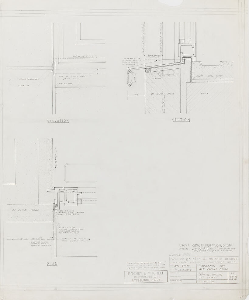
The image is a technical architectural drawing on a white background, detailing the construction of a typical window sill. The drawing is divided into three sections labeled "ELEVATION," "SECTION," and "PLAN," each showing a different view of the window sill construction.
The "ELEVATION" view shows the side of the window and sill, with annotations pointing to features like the "NOTCH. SUB FRAME," "CAULKING," "LINE OF TOP OF SILL," "LINE OF KAJOTA STONE BEHIND SILL," and "END OF SILL."
The "SECTION" view provides a cross-sectional cut of the window sill, highlighting the relationship between the "KAJOTA STONE TOOL," "BRICK," and other components, with annotations such as "LINE OF TOP OF PLATES TO BACK OF SILL" and "PLATE WELDED TO BACK OF SILL AT COLUMN."
The "PLAN" view shows a top-down view of the window sill, indicating elements like "1/2 KAJOTA STONE," "CAULKING ALONG SUB FRAME," "PLATER LINE," and "PORTION OF KAJOTA STONE BENEATH FILL."
Several lines of text are near the bottom right, including the dates "7/26/59" and "4/19/59" and some notes about revisions to the plates and sash.
At the bottom right, the architect is credited as "Walter Gropius & Marcel Breuer, Associated Architects, Cambridge, Mass." The residence is noted as being "For Mrs. Cecilia Frank." The drawing is described as a "Typical Window Sill Detail" and bears the number "117."
To the left of this, there's a note: "The contractor must verify all dimensions on the job, and report any discrepancies to the architects," alongside the name "Ritchey & Mitchell, Registered Architects, Pittsburgh, Penna."
Created by gemini-2.0-flash-lite on 2025-04-30
This is a detailed architectural drawing showcasing the window sill and its construction. The drawing contains three different views: an elevation, a section, and a plan. The design includes the use of "KAJOTA STONE" and mentions "brick" in the section view. The text annotations specify the different components, such as "notch sub-frame", "caulking", and dimensions like 1 1/4". The drawing is labeled with the architects' name and details about the project, including revisions and the project name "Residence For Mrs. Cecilia Frank." Overall, the drawing is a technical blueprint intended for construction purposes.
Text analysis
Amazon


