Machine Generated Data
Tags
Color Analysis
Categories
Imagga
| text visuals | 100% | |
Captions
Microsoft
created on 2018-03-22
| a close up of text on a white background | 72.8% | |
| a close up of text on a black background | 65.8% | |
| a close up of text on a white surface | 65.7% | |
OpenAI GPT
Created by gpt-4 on 2025-03-06
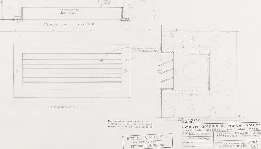
This image depicts a technical drawing or architectural plan that consists of a top view labeled as "PLAN OF FIXTURE," a front view labeled as "ELEVATION," and a side view labeled as "SECTION." These are typical views you would find in architectural or engineering drawings, showing different perspectives of the same object or structure. The plans are neatly executed with precise lines, annotations, and indications of dimensions. Triangular symbols for dimensions and various notes can be seen around the drawings, suggesting specifics on construction details. In the top right corner, there is a "NOTE" that directs the contractor to a small sheet shop for drawings of the fixture in all elements and details. The bottom left corner includes the credentials of the architectural firm responsible for the drawing, "Ritchey & Mitchell REGISTERED ARCHITECTS PITTSBURGH, PENNA." Across the bottom, the names "walter gropius & marcel breuer associated architects, cambridge, mass." specify the associated architects, and the address is given as "77 mt. vernon st." in Pittsburgh, PA. There are some additional details, which include a date, job number, and other information possibly related to the project administrative details. The project name mentioned is "J-S KENNEDY" with a date that appears as February (abbreviated as "FEB.") 23, 1937, and has been stamped with number 161. The drawing is specific to its purposes and would be used as part of a larger set of construction documents to relay design intentions and precise measurements for building or manufacturing the depicted object or structure.
Created by gpt-4o-2024-05-13 on 2025-03-06
This image is a technical drawing and blueprint created by the architectural firm of Walter Gropius & Marcel Breuer in collaboration with Ritchey & Mitchell, registered architects located in Pittsburgh, Pennsylvania. The drawings are part of the project for the Isadore H. and Lucille F. Pekarsky House in Pittsburgh, Pennsylvania, dated December 4, 1934. It was drafted by Kennedy and approved by H.P.S. The blueprint comprises three views of a structural fixture: 1. **Plan of Fixture**: This top-down view shows the layout of the fixture, marked with rectangles, and a label "REMOVEABLE LOUVERS." A note indicates "Two Half-Space Join" likely referring to specific parts coming together. The plan shows detailed positions and spatial relationships. 2. **Elevation**: This side view shows what the fixture looks like vertically. It is labeled "Elevation" and appears to focus on the external face of an element with louver configurations. 3. **Section**: The sectional drawing shows a cut-through view of the fixture, providing detailed insight into its construction from a viewpoint orthogonal to the plan. It notes the interior plaster drain elbows. A note in the top right corner specifies that "The Contractor Shall Submit Shop Drawings of this Fixture for the Architect's Approval, Showing All Elements in Detail." Key construction elements include dimensions, material indications, and annotations for accurate implementation. The drawing emphasizes ensuring the contractor verifies all dimensions and reports any discrepancies before proceeding with the work.
Anthropic Claude
Created by claude-3-haiku-20240307 on 2024-12-30
The image appears to be an architectural drawing or plan of a fixture or structure. It contains a detailed plan view and elevation view, along with some notes and details about the construction and specifications. The drawing includes technical information like dimensions and labels, but does not appear to depict any human subjects.
Created by claude-3-opus-20240229 on 2024-12-30
The image shows an architectural drawing or blueprint for what appears to be a fixture or furnace layout. The title at the top right indicates it is a "Plan of Fixture", likely referring to some industrial or manufacturing equipment. The main part of the drawing shows a top-down view of a rectangular structure, with dimensions and labels for different components like "Removable Louvers" and "Spray Pipes". Below that is an elevation view providing a side profile of the same structure. Additional annotations, dimensions and notes are included around the edges providing more technical details about the construction and elements. The drawing is credited to "Ritchey & Mitchell Registered Architects, Pittsburgh, Penna." in the bottom right corner. Overall, it is a detailed technical schematic laying out the design and specifications for building some type of industrial fixture, furnace or processing equipment based on the labels that can be seen. The stark black and white lines are typical of older blueprint-style technical drawings.
Created by claude-3-5-sonnet-20241022 on 2024-12-30
This is an architectural drawing or blueprint showing the plan and elevation views of what appears to be a fixture or built-in furniture piece. The drawing includes two main views: 1. A "Plan of Fixture" view from above, showing what appears to be a tub-shaped or elongated oval form with surrounding details. 2. An "Elevation" view showing horizontal lines or slats across the front face of the fixture. The drawing includes technical notes and specifications, and appears to be from an architectural firm in Cambridge, Massachusetts, with a stamp from "Ritchey & Mitchell" of Pittsburgh, Pennsylvania. There's also a note at the top right indicating that the contractor must submit shop drawings of the fixture for approval. The drawing is rendered in a technical drafting style typical of architectural documents, with clean lines and precise measurements, though the specific dimensions aren't clearly visible in this image.
Meta Llama
Created by us.meta.llama3-2-11b-instruct-v1:0 on 2025-03-13
The image presents a technical drawing of a room, likely for architectural or interior design purposes. The drawing is rendered in pencil on white paper and features several sections. **Key Features:** * **Elevation:** The elevation section shows the room's exterior, with a window and door prominently displayed. * **Plan of Fixture:** This section provides a detailed view of the room's layout, including the placement of furniture and fixtures. * **Section:** The section view offers a cross-sectional perspective of the room, highlighting the relationship between different elements. **Additional Details:** * **Note:** A handwritten note in the top-right corner provides additional information about the drawing, including the contractor's name and the date it was created. * **Walter Gropius & Marcel Breuer:** The names of the architects who created the drawing are listed in the bottom-right corner, along with their associated architects and the location of the building. * **Ritchey & Mitchell:** The names of the registered architects who created the drawing are listed in the bottom-center of the page, along with their location. **Overall:** The image provides a comprehensive view of the room's design, including its layout, elevation, and section. The inclusion of notes and credits adds context to the drawing, highlighting the involvement of various professionals in its creation.
Created by us.meta.llama3-2-90b-instruct-v1:0 on 2025-03-13
This image depicts a detailed architectural drawing of a fixture, showcasing its design and specifications. The drawing is divided into two main sections: the top section presents a plan view of the fixture, while the bottom section provides an elevation view. **Plan View:** * The plan view is oriented with the top edge facing north. * The fixture is rectangular in shape, featuring a rounded end on the left side. * A smaller rectangle is situated at the right end of the fixture, accompanied by a smaller square adjacent to it. * The fixture is positioned within a larger rectangular area, which is labeled as the "sub concrete" area. * The drawing includes various annotations and notes, including the phrase "PLAN OF FIXTURE" written in the center of the page. **Elevation View:** * The elevation view is also oriented with the top edge facing north. * This view provides a side-on perspective of the fixture, highlighting its vertical dimensions. * The drawing includes additional annotations and notes, including the phrase "ELEVATION" written below the elevation view. **Additional Details:** * The drawing features a logo in the bottom-right corner, which reads "RITCHEY & MITCHELL REGISTERED ARCHITECTS PITTSBURGH, PENNA." * A stamp in the bottom-right corner indicates that the drawing was approved by Walter Gropius and Marcel Breuer, associated architects from Cambridge, Massachusetts. * The drawing is dated December 4, 1951, and bears the name "Kennedy" as the creator. * The drawing number is 161, and it is part of a larger set of drawings for the Cecelia Frank House in Pittsburgh, Pennsylvania. Overall, this architectural drawing provides a detailed and accurate representation of the fixture's design and specifications, allowing architects and builders to construct the fixture according to the intended plans.
Amazon Nova
Created by amazon.nova-pro-v1:0 on 2025-01-12
The image is a drawing of a building's interior layout, specifically detailing the "Plan of Fixture" and "Elevation." The drawing is created on a white background with a grid-like structure to help with alignment and proportion. The drawing includes various annotations and measurements, indicating the dimensions and locations of different elements within the space. The drawing is labeled with the names of the architects, Walter Gropius and Marcel Breuer, and the date of the drawing, December 4, 1939. The drawing also includes a note at the top that reads "The contractor shall submit shop drawings of this fixture for the architects' approval, showing all elements in detail." This note suggests that the drawing is a preliminary design that requires further review and approval before construction can begin.
Created by amazon.nova-lite-v1:0 on 2025-01-12
The image appears to be an architectural drawing or blueprint for a building or structure. Here are the key details: - The drawing shows a plan view and elevation view of what appears to be a rectangular fixture or structure. - The plan view shows the dimensions and layout of the fixture, with measurements provided. - The elevation view shows the height and profile of the fixture. - The drawing is signed by "Kennedy" and includes the date "Dec 4-1951". - The drawing is for the "Beatrice Frank House" in Pittsburgh, Pennsylvania. - The architects listed are Walter Gropius and Marcel Breuer, who were prominent modernist architects. - The drawing includes notes and instructions for the contractor, indicating that the contractor must verify all dimensions and report any discrepancies to the architect. So in summary, this appears to be an architectural drawing for a fixture or structure designed by the architects Walter Gropius and Marcel Breuer for the Beatrice Frank House in Pittsburgh, Pennsylvania in 1951. The drawing provides the plan and elevation views, dimensions, and instructions for the contractor.
Text analysis
Amazon