Machine Generated Data
Tags
Color Analysis
Feature analysis
Amazon
Clarifai

Clarifai
| Whiteboard | 73.9% | |
Categories
Imagga
created on 2018-03-22
| text visuals | 100% | |
Captions
Microsoft
created by unknown on 2018-03-22
| a close up of text on a white surface | 60.4% | |
| a close up of text on a white background | 58.8% | |
| close up of text on a white surface | 56% | |
Clarifai
No captions written
Salesforce
Created by general-english-image-caption-blip on 2025-05-11
a photograph of a drawing of a plan for a house
Created by general-english-image-caption-blip-2 on 2025-06-28
a drawing of a building with a plan and floor plan
OpenAI GPT
Created by gpt-4 on 2025-03-08
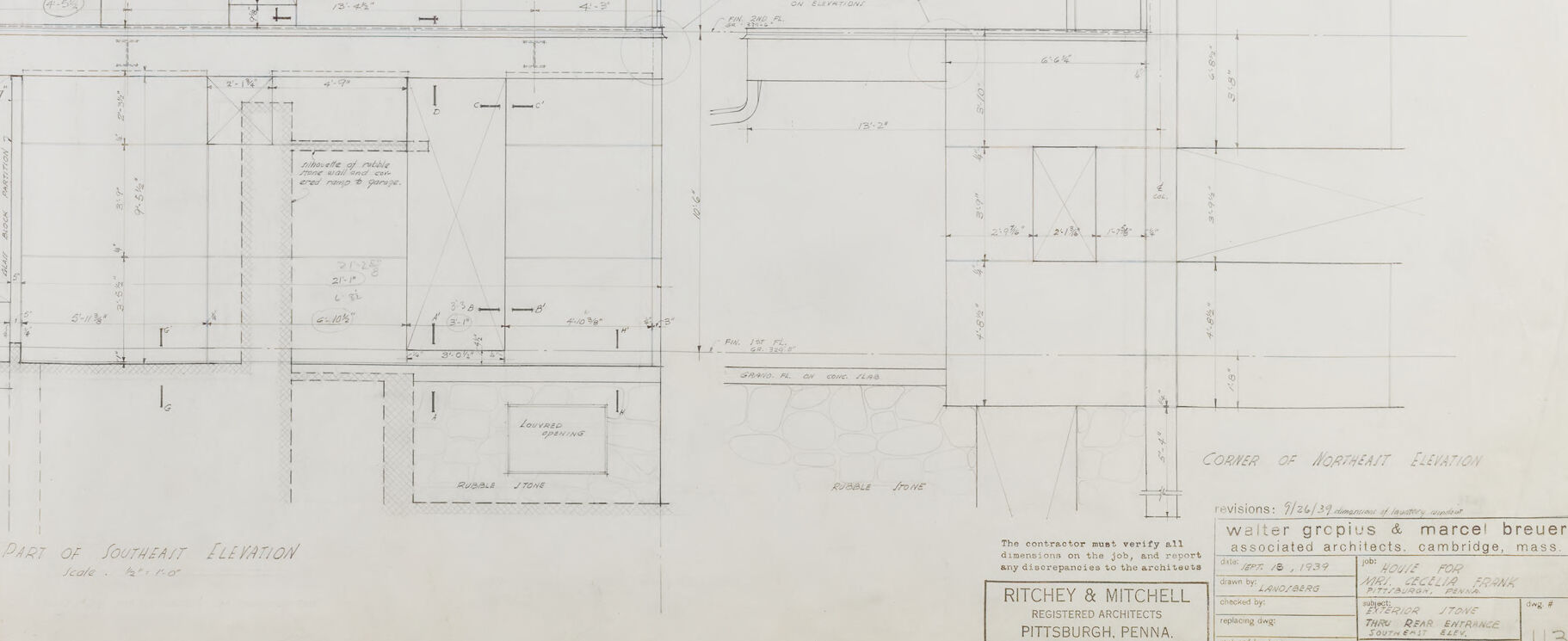
The image you provided is an architectural drawing or blueprint. The drawing appears to show the elevation view of a building, specifically the "Part of South-East Elevation," as noted on the plan itself. Elevation views are orthographic projections (without perspective) of the sides of buildings and are used to depict the exterior faces of the structure.
This technical drawing includes detailed measurements, indicating dimensions for various elements of the building. The lines, symbols, and text are all typically used to convey construction and design details to builders and contractors. Various annotations and specifications are also present, which would be critical for understanding the design intent and for guiding construction.
In the lower right corner, there's information regarding the architects, project title, and other details:
- Client: The Estey Co.
- Architects: "Ritchey & Mitchell" and "Walter Gropius & Marcel Breuer Associated Architects, Cambridge, Mass."
- The architectural firm's location: "Pittsburgh, Penna."
This suggests that the drawing relates to a collaborative project involving well-known figures in architecture, Walter Gropius and Marcel Breuer, who were influential in the Bauhaus movement, and completed by Ritchey & Mitchell from Pittsburgh.
It's important to note that while I can describe the elements of the drawing, I cannot place it within a historical context or provide specific details about the significance of the building without additional research.
Created by gpt-4o-2024-05-13 on 2025-03-08
This image appears to be an architectural drawing or blueprint. The detailed diagram showcases structural elements and measurements in a technical, line-drawn format. Annotations, dimensions, and labels are meticulously noted, likely indicating various components and materials, construction specifications, and section views of a building.
In the bottom right corner, there is a title block that includes information about the architects (Walter Gropius & Marcel Breuer), the associated architecture firm (Ritchey & Mitchell, Pittsburgh, Pennsylvania), and other project details such as revisions and drawing numbers. The title block identifies the drawing as part of the documentation for a specific architectural project and includes references like "Part of Southeast Elevation" and "Corner of Dormitory Elevation."
Anthropic Claude
Created by us.anthropic.claude-3-5-sonnet-20241022-v2:0 on 2025-06-24
This image appears to be an architectural drawing or blueprint showing elevation views of a building. The drawing is labeled "Ritchey & Mitchell" from Pittsburgh, Pennsylvania, and was created by Walter Gropius & Marcel Breuer, associated architects from Cambridge, Massachusetts. It shows detailed technical drawings with various measurements and dimensions marked throughout. The drawing appears to show different sections of a building's exterior elevation, with precise measurements and construction details. The drawing is done in a professional architectural style with clean lines and appears to be from a larger set of construction documents, as indicated by the drawing number 1/3 in the bottom right corner. The drawing contains both plan and elevation views, with careful attention to structural and dimensional details.
Created by claude-3-haiku-20240307 on 2024-12-30
This image appears to be a detailed architectural or engineering blueprint or technical drawing. It shows various plans, elevations, and cross-sections of what seems to be a structural or mechanical design. The drawing contains precise measurements, grid lines, and technical annotations. It looks to be the work of a professional engineer or architect, with the name "Ritchey & Mitchell" credited at the bottom.
Created by claude-3-opus-20240229 on 2024-12-30
The image shows an architectural blueprint or floor plan for what appears to be a residential building, likely a house. The blueprint includes detailed dimensions, measurements, and layout markings for various rooms and spaces within the structure, such as bedrooms, bathrooms, living areas, and a kitchen. The plan is drawn in a precise, technical style typical of architectural drawings. At the bottom, there is a title block with the names "Ritchey & Mitchell" listed, presumably identifying the architects or firm responsible for the design. Overall, the image provides a clear, scaled representation of the proposed layout and spatial relationships within the building.
Created by claude-3-5-sonnet-20241022 on 2024-12-30
This is an architectural drawing showing section views and elevations. The drawing appears to be a technical blueprint or construction document, with detailed measurements and dimensions marked throughout. The drawing is labeled "BASE OF EQUIPMENT ELEVATION" and includes various architectural details and specifications. The architects listed on the drawing are Walter Gropius & Marcel Breuer, associated architects from Cambridge, Mass. The project appears to be for Ritchey & Mitchell in Pittsburgh, Pennsylvania. The drawing includes detailed line work showing structural elements, equipment bases, and various architectural components, all drawn to scale with precise measurements indicated.
Meta Llama
Created by us.meta.llama3-2-11b-instruct-v1:0 on 2025-03-15
The image presents a detailed floor plan for the Church of Asphalt Elementary, showcasing the architectural design and layout of the building. The plan is drawn to scale and includes various rooms, corridors, and other features.
- Scale: The floor plan is drawn to a scale of 1/4 inch = 1 foot, indicating that each quarter inch on the plan represents one foot in real life.
- Rooms and Corridors: The plan includes several rooms, including classrooms, offices, and restrooms, as well as corridors that connect them.
- Doors and Windows: The plan shows the location and size of doors and windows, providing information on how the building will be ventilated and lit.
- Dimensions: The plan includes measurements for each room and corridor, allowing for precise construction and renovation.
- Labels: The plan includes labels for each room and feature, making it easier to identify and understand the different components of the building.
- Legend: A legend is provided at the bottom of the plan, explaining the symbols and abbreviations used throughout the drawing.
- Title: The title of the plan, "Church of Asphalt Elementary," is prominently displayed at the top of the page, indicating the purpose and scope of the design.
- Date: The date of the plan is not explicitly stated, but it appears to be an older document, given the style of the drawing and the materials used.
- Author: The author of the plan is not identified, but it is likely that it was created by an architect or engineer who specializes in educational facilities.
- Location: The location of the Church of Asphalt Elementary is not specified, but it is likely that it is located in a urban or suburban area, given the size and layout of the building.
- Purpose: The purpose of the plan is to provide a detailed and accurate representation of the building's design, allowing for effective construction, renovation, and maintenance.
Overall, the floor plan provides a comprehensive overview of the Church of Asphalt Elementary's design and layout, making it an essential tool for architects, engineers, contractors, and other stakeholders involved in the project.
Created by us.meta.llama3-2-90b-instruct-v1:0 on 2025-03-15
The image presents a technical drawing of a building's floor plan, showcasing the layout and dimensions of various rooms and spaces. The drawing is rendered in black ink on white paper, with precise lines and measurements that provide a detailed understanding of the building's design.
Key Features:
- Floor Plan: The drawing depicts a floor plan with multiple rooms, corridors, and staircases.
- Dimensions: Measurements are provided for each room and corridor, allowing for accurate scaling and planning.
- Labels: Rooms and spaces are labeled with descriptive text, such as "Lobby" or "Office."
- Symbols: Various symbols are used throughout the drawing to represent different elements, such as doors, windows, and electrical outlets.
- Scale: A scale is included in the bottom-right corner, indicating the ratio of the drawing to the actual size of the building.
- Title Block: A title block is located in the bottom-right corner, containing information about the project, including the architect's name, date, and location.
Overall Impression:
The technical drawing provides a comprehensive overview of the building's design, allowing architects, engineers, and contractors to plan and execute the construction process with precision. The level of detail and accuracy in the drawing demonstrates a high level of professionalism and attention to detail.
Amazon Nova
Created by amazon.nova-lite-v1:0 on 2025-01-12
This is an architectural drawing, likely a floor plan or elevation. It features a grid-like layout with various lines, measurements, and annotations. The drawing includes dimensions, labels, and notes that provide information about the structure's design and construction. The drawing is labeled "Part of South Elevation," indicating that it represents a portion of the building's southern elevation. The drawing also includes the names of the architects, "Walter Gropius & Marcel Breuer," and the location, "Cambridge, Mass." The drawing is signed by "Ritchey & Mitchell," who were registered architects in Pittsburgh, Pennsylvania.
Created by amazon.nova-pro-v1:0 on 2025-01-12
The image shows a detailed architectural blueprint, possibly for a residential or commercial building. The blueprint includes various sections and elevations of the structure, providing a comprehensive view of the design. The blueprint is labeled with dimensions, annotations, and other relevant information, indicating that it is a professional architectural drawing intended for construction or renovation purposes.
Google Gemini
Created by gemini-2.0-flash on 2025-06-02
The image is an architectural drawing, likely a blueprint, showing elevation details of a building. The drawing is executed in a clean, technical style with fine lines and precise measurements. The drawing is labeled as "Corner of Northeast Elevation" and "Part of Southeast Elevation," indicating it shows different views of the building's corner. The drawing includes detailed notations, dimensions, and specifications, which are typical for construction documents. It seems to be a meticulous representation intended for construction purposes. The drawing is credited to Walter Gropius & Marcel Breuer associated architects, and Ritchey & Mitchell, registered architects of Pittsburgh, Penna.
Created by gemini-2.0-flash-lite on 2025-06-02
Here's a description of the image:
Overall:
The image is a detailed architectural blueprint, likely for a building's exterior elevation. It's a black and white drawing filled with precise lines, dimensions, annotations, and symbols, typical of architectural plans. The sheet is aged, showing some discoloration and a slightly uneven surface.
Key Elements & Features:
- Elevations: The primary focus seems to be the elevation of a building's facade or corner.
- Dimensions and Markings: The blueprint is covered in measurements (feet and inches), indicating the lengths and heights of various building elements. There are also labels and notes describing materials, construction details, and specific components.
- Building Details: The drawing details the structure of the building, including structural columns, horizontal beams, window openings, and roofing features.
- Annotations and Symbols: Architects' notes and various symbols are present, offering additional information about the building.
- Titles & Identification: There are titles like "Part of Southeast Elevation" and "Corner of Northeast Elevation" indicate the viewpoint. A legend at the bottom provides identifying information about the project and the architects involved.
- Architectural Style: The style leans towards modernism.
Signage:
- The architects are Walter Gropius and Marcel Breuer, associated architects, Cambridge, mass.
- The firm name Ritchey & Mitchell, registered architects, Pittsburgh, penna.
- Title "House for ... "
In summary: The image is a technical drawing representing an architectural project. It provides detailed information about the building's structure, dimensions, and design features, likely intended for construction purposes.
Mistral Pixtral
Created by us.mistral.pixtral-large-2502-v1:0 on 2025-05-30
The image is a detailed architectural floor plan drawing. Here's a breakdown of the key elements:
Title and Identification:
- The drawing is titled "Plan of Picture Gallery."
- It is dated "June 1939."
- The architects are identified as Walter Blairman and Maurice Brauer.
- The drawing is associated with the firm "Mitchell & Mitchell," located in Pittsburgh, Pennsylvania.
Scale and Drawing Number:
- The scale of the drawing is noted as "1/4" = 1' - 0".
- The drawing number is "115."
Layout and Dimensions:
- The floor plan includes various rooms and spaces, each with specific dimensions.
- The layout appears to be a rectangular space divided into sections, likely representing different areas within the picture gallery.
- There are detailed measurements provided for walls, doorways, and other architectural features.
Annotations and Details:
- The drawing includes various annotations and labels, such as "Picture Gallery," "Toilet," and "Storage."
- There are notes and specifications regarding the construction and materials, such as "2x4 stud partition" and "2x6 floor joists."
- The plan also includes symbols and lines indicating structural elements like walls, doors, and possibly electrical or plumbing features.
Additional Information:
- The drawing is stamped with the approval of the architects and the firm.
- There is a note indicating that the contractor was required to comply with the conditions of the contract.
This floor plan provides a comprehensive layout of a picture gallery, including detailed dimensions and specifications necessary for construction and planning purposes.
Qwen
Created by Qwen/Qwen2.5-VL-7B-Instruct on 2025-07-20
This is an architectural blueprint titled "Corner of Northeast Elevation." It is a detailed drawing of the exterior design and structural details of a building, focusing on the northeastern corner. The blueprint includes:
- Dimensions and measurements of various walls, windows, and structural elements.
- Notes and annotations for specific features, such as "Rubble Stone" and "Louvre Openings."
- Sectional views showing the detailed construction of the building elements, such as walls, foundations, and roof structures.
- Notes on the scale of the drawing, which is 1/2" = 1'-0" (1/2 inch equals 1 foot).
- The name "Walter Gropius & Marcel Breuer" is mentioned, indicating the architects responsible for the design.
- The date "10/7/39" is present, suggesting it was drawn on October 7, 1939.
- The name "Ritchey & Mitchell, Registered Architects" from Pittsburgh, Pennsylvania, is included as well.
The blueprint is used for construction, detailing the precise measurements and specifications required for building the structure. It is a technical document that would be used by contractors to build the building according to the plans.
Created by Qwen/Qwen2.5-VL-72B-Instruct on 2025-07-20
This image is a detailed architectural drawing, likely a section or elevation view of a building. It includes precise measurements, labeled dimensions, and various construction details. The drawing is divided into two main sections: the "Part of Southeast Elevation" on the left and the "Corner of Northeast Elevation" on the right.
Key features of the drawing include:
- Detailed line work showing the structural elements of the building.
- Annotations and labels indicating specific parts of the building, such as "Rubble Stone," "Louvered Opening," and "Fin. Brad Al. Ceiling."
- Scales and dimensions are provided for accurate construction.
- The drawing is attributed to Walter Gropius & Marcel Breuer, with Ritchey & Mitchell as registered architects from Pittsburgh, Pennsylvania.
- The date on the drawing is September 18, 1939, and it is for a project named "House for Mrs. Cecelia Frank."
The drawing is comprehensive, showing various levels and sections of the building, including the foundation, walls, and roof details.
Text analysis
Amazon