Machine Generated Data
Tags
Color Analysis
Categories
Imagga
| text visuals | 100% | |
Captions
Microsoft
created on 2018-03-22
| a close up of text on a white surface | 64.8% | |
| a close up of text on a white background | 63.2% | |
| close up of text on a white surface | 60.3% | |
OpenAI GPT
Created by gpt-4 on 2025-03-08
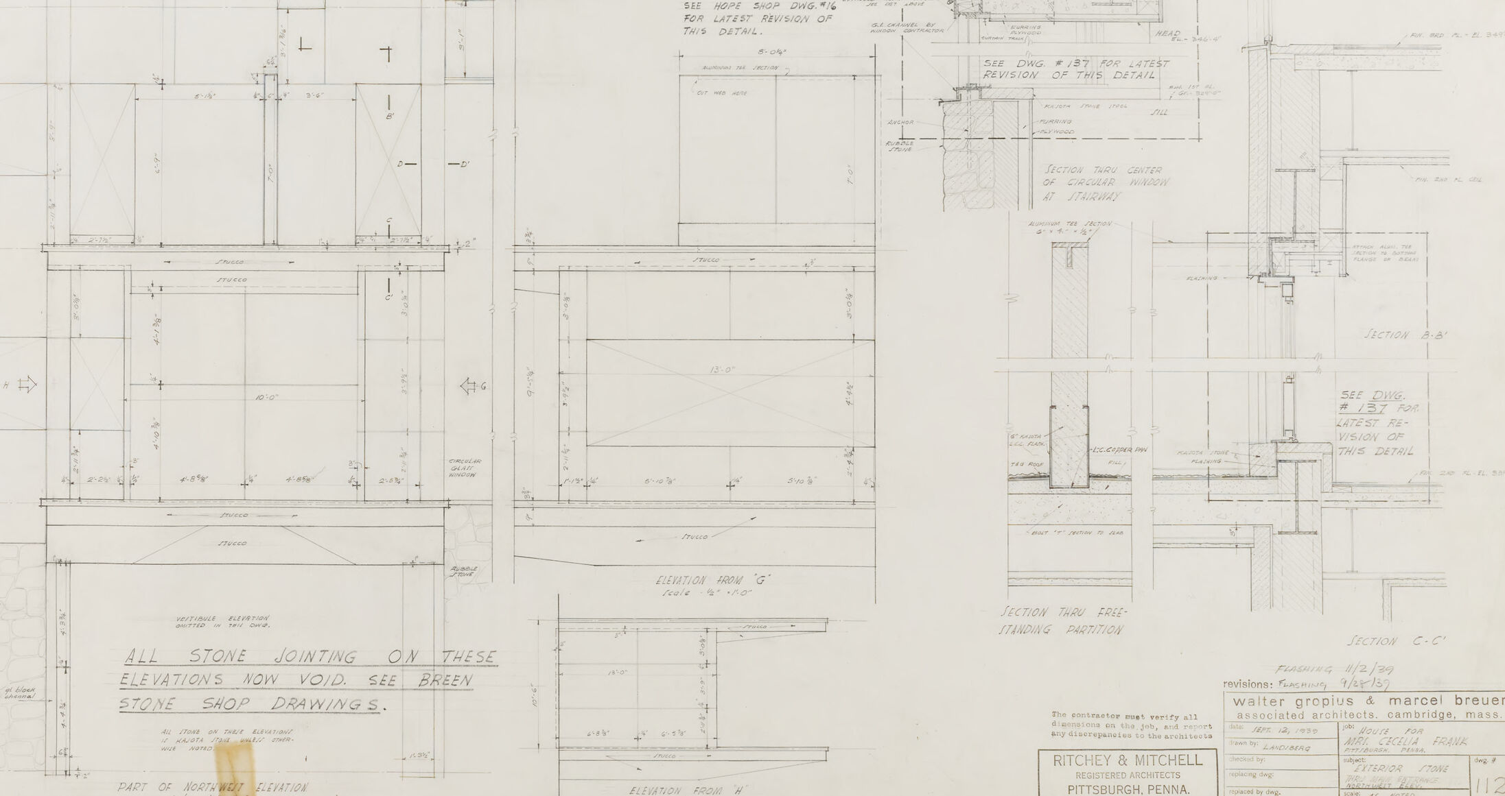
This image shows an architectural drawing or blueprint. It contains a series of detailed elevation views and sectional drawings/diagrams. These types of technical drawings are used for the construction of buildings and structural elements. The drawings include a variety of annotations, measurements, and details that provide specific information about dimensions and construction techniques required to accurately build or manufacture the components depicted. The text at the bottom indicates that it is associated with the architectural practice of Walter Gropius and Marcel Breuer. The architectural firm is Ritchey & Mitchell based in Pittsburgh, Pennsylvania. There are notes on revisions and refer to stone jointing on the elevations, which is now void and references stone shop drawings. These documents are crucial in the planning and execution phases of a construction project, ensuring that all parts of the structure are correctly aligned and built according to precise specifications.
Created by gpt-4o-2024-05-13 on 2025-03-08
This image depicts an architectural technical drawing consisting of detailed plans, elevations, and sections for a building or structure. It includes precise measurements, structural annotations, and specifications. The drawing appears to be created by architects, with the names Walter Gropius and Marcel Breuer noted at the bottom, indicating their involvement as associated architects. There are specific areas where revisions and additional details are required, as mentioned in the notes on the drawing. The primary purpose of this document is to provide accurate instructions for the construction and assembly of various building components, particularly focusing on stone jointing details as mentioned in the document's notes. The drawing is also marked with the name Ritchie & Mitchell, Pittsburgh Architects, indicating their role in the architectural design.
Anthropic Claude
Created by claude-3-haiku-20240307 on 2024-12-30
The image appears to be an architectural drawing or blueprint, containing various technical diagrams and detailed measurements. It includes multiple views and cross-sections of a structure, likely a building or construction project. The blueprint is annotated with notes, such as "All stone jointing on these elevations now void, see green size stop drawing s.", indicating some changes or modifications to the original design. The drawing is signed by "RITCHEY & MITCHELL" and appears to be dated.
Created by claude-3-opus-20240229 on 2024-12-30
The image shows architectural drawings and plans for what appears to be stone jointing on building elevations. The plans include front, side and detail views with various measurements and annotations. A note at the bottom states "All stone jointing on these elevations you void see green penci shop drawings", suggesting these are draft or preliminary drawings. The plans are attributed to "Ritchey & Mitchell", likely an architectural firm, with their office address in Pittsburgh, Pennsylvania provided in the title block.
Created by claude-3-5-sonnet-20241022 on 2024-12-30
This is an architectural drawing or blueprint showing various technical details and elevations. The drawing appears to be for a project in Pittsburgh, Pennsylvania, with "Ritchey & Mitchell" noted on the title block. It's drawn by Walter Gropius & Marcel Breuer Associates Architects from Cambridge, Massachusetts. The drawing contains multiple detailed sections and elevations showing stone jointing details and construction specifications. There's a note on the drawing stating "ALL STONE JOINTING ON THESE ELEVATIONS NOW VOID. SEE GREEN STONE SHOP DRAWINGS." The sheet includes various cross-sections and detailed views of what appears to be building elements, with precise measurements and construction notes. The drawing is done in pencil on paper and shows professional architectural drafting techniques typical of mid-20th century architectural documentation. The drawing is labeled as sheet 1/2, suggesting it's part of a larger set of construction documents.
Meta Llama
Created by us.meta.llama3-2-11b-instruct-v1:0 on 2025-03-16
The image presents a detailed architectural drawing of a building, showcasing its floor plan and elevations. The drawing is rendered in pencil on a sheet of paper, with various sections and details labeled for clarity. **Key Features:** * **Floor Plan:** The drawing includes a floor plan, which provides an overview of the building's layout. This section is likely to include information about the rooms, corridors, and other spaces within the building. * **Elevations:** The drawing also features elevations, which are side views of the building that show its height and exterior features. These elevations may include details such as windows, doors, and architectural elements like columns or arches. * **Labels and Notations:** Throughout the drawing, there are labels and notations that provide additional information about the building's design and construction. These may include measurements, materials, and other relevant details. * **Scale:** The drawing includes a scale, which allows the viewer to understand the relative sizes of the different elements within the building. * **Architectural Style:** Based on the drawing, it appears that the building is designed in an architectural style that emphasizes clean lines, minimal ornamentation, and a focus on functionality. This style is often associated with modernist or contemporary architecture. **Conclusion:** Overall, this architectural drawing provides a detailed and informative representation of a building's design and construction. It is likely to be used by architects, engineers, and contractors to plan and execute the building's construction.
Created by us.meta.llama3-2-90b-instruct-v1:0 on 2025-03-16
The image depicts a technical drawing of a building's floor plan, likely created by an architect or engineer. The drawing is rendered in black ink on white paper and features various symbols, notations, and measurements that provide detailed information about the building's design and construction. **Key Features:** * **Floor Plan:** The drawing shows the layout of the building's floors, including rooms, corridors, stairwells, and other features. * **Symbols and Notations:** The drawing includes various symbols and notations that indicate different aspects of the building's design, such as door and window locations, electrical outlets, and plumbing fixtures. * **Measurements:** The drawing includes precise measurements of the building's dimensions, including room sizes, hallway widths, and stairwell heights. * **Architectural Details:** The drawing also includes detailed information about the building's architectural features, such as column locations, beam sizes, and roof pitches. **Purpose:** The purpose of this technical drawing is to provide a detailed and accurate representation of the building's design and construction. It serves as a blueprint for contractors, builders, and other stakeholders involved in the construction process, ensuring that the building is built according to the architect's or engineer's specifications. **Conclusion:** In conclusion, the image depicts a technical drawing of a building's floor plan, which is an essential tool for architects, engineers, and contractors. The drawing provides detailed information about the building's design and construction, ensuring that the building is built safely and efficiently.
Amazon Nova
Created by amazon.nova-lite-v1:0 on 2025-02-28
The image is a detailed architectural drawing of a building's section. The drawing includes various labeled sections such as "SECTION A-A," "SECTION B-B," and "SECTION C-C." Each section provides a cross-sectional view of different parts of the building, showing the internal structure, including walls, floors, and possibly roofing. The drawing also includes annotations and notes, such as "ALL STONE JOINTING ON THESE ELEVATIONS NOW VOID SEE GREEN STONE SHOP DRAWINGS," indicating specific instructions for the stonework. The drawing is marked with the date "February 1976" and the name "Walter Gropius & Marcel Breuer," suggesting it was created by these architects. The drawing also includes a table with details such as "RITCHEY & MITCHELL, REGISTERED ARCHITECTS, PITTSBURGH, PENNA." This suggests that the document is a professional architectural drawing used for construction purposes.
Created by amazon.nova-pro-v1:0 on 2025-02-28
The image shows a blueprint for a building. The blueprint is divided into several sections, each containing different details and measurements. The top section contains a note that reads, "ALL STONE JOINTING ON THESE ELEVATIONS NOW VOID SEE BREEN STONE SHOP DRAWINGS." The bottom section contains the name of the architect, Walter Gropius, and the name of the company, Mitchell & Mitchell. The blueprint also contains a scale and a date.
Text analysis
Amazon