Machine Generated Data
Tags
Color Analysis
Categories
Imagga
| text visuals | 100% | |
Captions
Microsoft
created by unknown on 2018-03-23
| a close up of a map | 85.7% | |
| close up of a map | 83.2% | |
| a map with text | 77.4% | |
Clarifai
created by general-english-image-caption-blip on 2025-05-05
| a photograph of a drawing of a plan for a bathroom | -100% | |
OpenAI GPT
Created by gpt-4 on 2025-03-06
This image is a technical drawing or architectural blueprint detailing the design of a light fixture. It is a high-level technical document that includes a series of different views: elevation, sections, and detailed construction notes that specify materials, finishes, and dimensions.
The drawing features several key elements:
- Elevation view (full size scale) showing the front view of the light fixture.
- Section views (marked as A-A at center line), providing cross-sectional details of the fixture to reveal interior construction.
- Specifications for materials such as chrome-plated finishes, satin finishes, reinforcing rods, gasket material, and the type of bolts to use.
- Notes that offer additional information, for instance, the size of pipes and bulbs to be used, and instructions to allow cable to enter junction box where necessary.
- Annotations indicating the scale for various parts of the drawing (e.g., full size, 1/4" = 1'-0" for the location of fixtures).
The document references 'Walter Gropius & Marcel Breuer, Associated Architects, Cambridge, Mass.', identifying notable figures in the field of architecture. It is dated 'Sept. 29.1938', and there are some revisions noted, dated 'Nov. 7.1938'.
The drawing was created for a residence detailed in the bottom right corner, but for privacy and compliance with guidelines, that information won't be disclosed.
Architectural drawings like this are crucial in the construction and manufacturing process, ensuring that all components are made to exact specifications for proper assembly and installation.
Created by gpt-4o-2024-05-13 on 2025-03-06
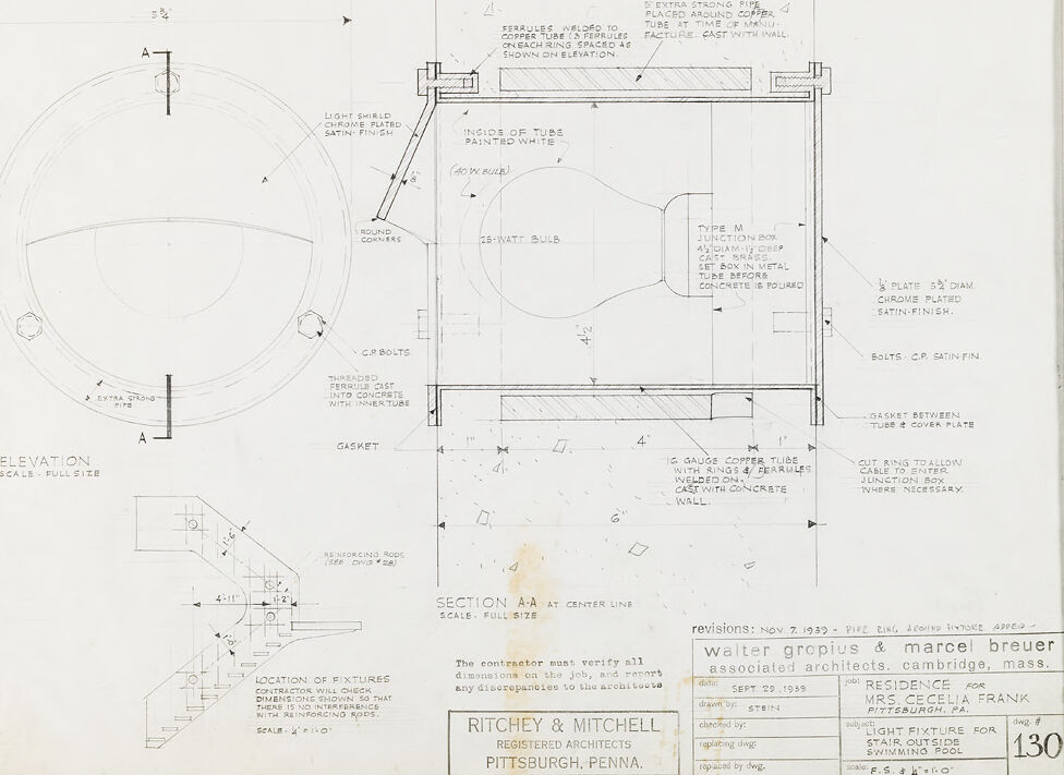
This image is a technical architectural drawing of a light fixture, specifically designed for installation in a stair outside of a swimming pool. The drawing is highly detailed and includes several views, measurements, and notes on construction and installation.
Key elements and notes visible in the drawing include:
Elevation View (Scale: Full Size): This is the frontal view of the light fixture showing circular shape and structural details such as bolts and a light shield with a chrome-plated satin finish.
Section A-A (Scale: Full Size): A cross-sectional view of the fixture along the centerline indicated as A-A. It shows the internal configuration of the light fixture including the light bulb and associated components.
Detailed Notes:
- Light fixture is for a 25-watt bulb.
- Gasket details and a chrome-plated ⅜" diameter plate.
- Type M junction box with metal casting required before concrete is poured.
- Copper tube construction with chrome plating.
- Specifications for threading ferrule cast into concrete.
Component Details:
- Round corners.
- Bolts are described as CP (chrome plated) satin finish.
- Use of 18 gauge copper tube.
Installation Guidance:
- Location of fixtures in relation to reinforcing rods in concrete.
- Contractual obligations for the contractor to verify dimensions and other reference points before construction.
Architectural Firms:
- The drawing comes from Ritchey & Mitchell Registered Architects based in Pittsburgh, Pennsylvania.
- Associated architects listed are Walter Gropius and Marcel Breuer based in Cambridge, Massachusetts.
Project Information:
- The drawing is specified for the residence of Mrs. Cecelia Frank in Pittsburgh, PA.
- Dated September 29, 1939.
- Marked revision date of November 7, 1939, with additional notes on pipe engineering, etc.
- Drawing number: 130 F.S. 1’=1’-0”.
This thorough and highly technical drawing would be instrumental for engineers and contractors involved in installing the light fixture correctly and ensuring safety and design specifications are met.
Anthropic Claude
Created by claude-3-haiku-20240307 on 2024-12-30
The image appears to be an architectural drawing or technical diagram. It contains detailed technical specifications, measurements, and schematic diagrams for various components and parts. The drawing seems to be related to plumbing or pipe installation, with references to a "copper tube", "junction box", and other construction-related elements. The overall layout and technical nature of the drawing suggest it is an engineering or construction-related document, likely used for planning or installation purposes.
Created by claude-3-opus-20240229 on 2024-12-30
The image shows an architectural drawing or blueprint. It contains multiple views including an elevation view, floor plan, and section view of what appears to be a bathroom based on the bathtub and fixtures shown. Various dimensions and technical notes are included on the plans. The title block in the lower right identifies this as a project by the architecture firm Ritchey & Mitchell located in Pittsburgh, Pennsylvania. The project is titled "Walter gronius & marcel breuer associated architects exhibition mass."
Created by claude-3-5-sonnet-20241022 on 2024-12-30
This is an architectural drawing/blueprint showing technical details for what appears to be a lighting fixture installation. The drawing includes both an elevation view and a section view (labeled A-A) showing various components including a light shield, junction box, and mounting details. The plans are drawn at full scale and include specific measurements and notes about materials like "chrome plated satin finish" and "inside of tube painted white."
The document is from the architectural firm Walter Gropius & Marcel Breuer Associated Architects in Cambridge, and was drawn for a residence project in Pittsburgh, PA. The drawing is specifically for a spotlight fixture for stairs outside a swimming pool. It's dated September 22, 1939, with revisions noted from November 7, 1939. The drawing number is 130, and it was produced by Ritchey & Mitchell, Registered Architects from Pittsburgh, Pennsylvania.
The technical detail shows precise measurements and specifications for the installation, including gasket placement, bolt locations, and specific material finishes required for the outdoor fixture.
Meta Llama
Created by us.meta.llama3-2-11b-instruct-v1:0 on 2025-03-13
The image presents a technical drawing for a light fixture, specifically designed for a stair outside the swimming pool. The drawing is created by Ritchey & Mitchell, Registered Architects, Pittsburgh, Penna., and features a detailed design with various components labeled.
- Light Shield
- The light shield is a circular component with a satin finish.
- It is positioned on the left side of the drawing.
- Copper Tube
- The copper tube is a key component of the light fixture.
- It is wrapped with ferrules, which are shown on elevation.
- The tube is painted white and has a diameter of 2 inches.
- Type M Junction Box
- The Type M junction box is a rectangular component with a metal tube before concrete is poured.
- It is located on the right side of the drawing.
- Bolts
- The bolts are used to secure the light fixture to the concrete wall.
- They are labeled as C.P. satin fin.
- Gasket
- The gasket is a circular component that seals the light fixture to the concrete wall.
- It is labeled as 2 watt bulb.
- Ferrules
- The ferrules are used to wrap the copper tube.
- They are shown on elevation.
- Concrete Wall
- The concrete wall is the surface to which the light fixture is attached.
- It is labeled as concrete wall.
In summary, the image presents a detailed technical drawing for a light fixture designed for a stair outside the swimming pool. The drawing includes various components, such as the light shield, copper tube, Type M junction box, bolts, gasket, ferrules, and concrete wall, which are all labeled and described in detail.
Created by us.meta.llama3-2-90b-instruct-v1:0 on 2025-03-13
The image presents a technical drawing of a light fixture, accompanied by detailed specifications and measurements. The drawing is divided into two main sections: the left side features a circular elevation view, while the right side displays a rectangular section view.
Circular Elevation View (Left Side)
- The circular elevation view is labeled "ELEVATION SCALE - FULL SIZE" and provides a detailed representation of the light fixture's design.
- The drawing includes various annotations, such as "A" and "5%", which likely refer to specific dimensions or features of the fixture.
- A smaller inset drawing at the bottom left corner appears to be a detailed view of a particular component, possibly a mounting bracket or electrical connection.
Rectangular Section View (Right Side)
- The rectangular section view is labeled "SECTION AA AT CENTER LINE SCALE - FULL SIZE" and offers a cross-sectional view of the light fixture.
- This section view reveals the internal structure of the fixture, including the placement of electrical components, such as bulbs and wiring.
- The drawing also includes annotations, such as "TYPE M JUNCTION BOX" and "25-WATT BULB", which provide additional information about the fixture's design and functionality.
Specifications and Measurements
- The drawing includes a table with specifications and measurements for the light fixture, including its size, material, and electrical requirements.
- The table is labeled "RITCHEY & MITCHELL REGISTERED ARCHITECTS PITTSBURGH, PENNA." and includes a revision date of November 7, 1939.
- The drawing also features a stamp from the architects, indicating that it was approved by Walter Gropius & Marcel Breuer on September 22, 1939.
Overall, the image provides a detailed and technical representation of a light fixture, including its design, specifications, and measurements. The drawing is likely intended for use by architects, engineers, or contractors involved in the construction or installation of the fixture.
Amazon Nova
Created by amazon.nova-pro-v1:0 on 2025-01-13
The image is a detailed architectural drawing of a circular structure, likely a light fixture for a swimming pool. The drawing includes various sections and annotations, providing precise measurements and specifications for the construction of the fixture. The structure is composed of multiple concentric circles, with the outermost circle having a diameter of approximately 130 inches. The inner circles are progressively smaller, with the innermost circle having a diameter of approximately 40 inches. The drawing includes annotations for the materials used, such as copper tubing, chrome-plated metal, and concrete. There are also annotations for the electrical components, such as the 25-watt bulb and the junction box. The drawing is dated September 29, 1939, and is signed by the architects, Walter Gropius and Marcel Breuer.
Created by amazon.nova-lite-v1:0 on 2025-01-13
The image appears to be a technical drawing or blueprint for a swimming pool installation. The drawing contains various details and specifications for the installation of a light fixture and other components in the pool area. Some key details from the image include:
- The drawing shows a plan view of the pool area with dimensions and measurements labeled.
- There are details for a light fixture to be installed above the pool, including the type of bulb, mounting hardware, and electrical connections.
- There are notes specifying the use of extra strong pipe, copper tubing, and chrome-plated hardware.
- The drawing includes details for reinforcing rods to be embedded in the concrete wall around the pool.
- The architect's name and address are listed as Walter Gropius and Marcel Breuer, associated architects in Cambridge, Massachusetts.
- The drawing is dated September 29, 1939 and has a revision date of November 7, 1939.
Overall, the image provides technical specifications and details for the installation of a light fixture and other components in a swimming pool area, likely for a residential project. The drawing was created by the architectural firm of Walter Gropius and Marcel Breuer in 1939.
Google Gemini
Created by gemini-2.0-flash-lite on 2025-05-06
Here is a description of the image:
Overview:
The image is a detailed architectural blueprint of a light fixture design. The drawing includes various views, sections, and annotations to clarify the construction and assembly of the fixture. It appears to be for a residential project, likely for the exterior stairs of a swimming pool area.
Key Components and Features:
- Elevation View: A full-size elevation shows the light fixture's overall shape, including a circular light shield and a cylindrical base.
- Section A-A: This section cut provides a cross-sectional view of the fixture, revealing its internal components and how they are assembled.
- Light Shield: A chrome-plated light shield, painted white on the inside, is a prominent feature.
- Light Bulb: The blueprint specifies both a 25-watt and a 40-watt bulb.
- Copper Tube: The design makes extensive use of copper tubing for housing the electrical components and providing structural support.
- Junction Box: A Type M junction box is included to connect the electrical wiring.
- Mounting Plate: A satin-finished chrome-plated plate is used for mounting the fixture.
- Gaskets: Gaskets are indicated to ensure a tight seal between components.
- Reinforcing Rods: Reinforcing rods are included in the design and are referenced to other drawings for details.
- Construction Details: The blueprint includes detailed information on how the fixture is to be constructed, including the use of ferrules, welding, and casting with concrete.
- Staircase Detail: A separate small drawing shows a sectional view of a staircase where the light fixture is to be mounted.
- Annotations: The blueprint is extensively annotated with notes, dimensions, and material specifications, which will likely need to be verified by a contractor.
Additional Information:
- Project: The light fixture is for the residence of Mrs. Cecelia Frank in Pittsburgh, PA.
- Architects: Walter Gropius & Marcel Breuer are the associated architects.
- Scale: The main elevation view and section view have a scale of "Full Size", and the stair detail has a scale of 1" = 1'0".
- Revisions: The revisions indicate that changes were made to the design in November 1939.
- Date: The drawings were created on Sept 29, 1939.
Overall Impression:
This is a meticulously detailed architectural drawing that provides all the information necessary for a skilled contractor to build and install the light fixture. The blueprint demonstrates a level of care and precision consistent with the work of the architects.
Created by gemini-2.0-flash on 2025-05-06
Here is a description of the image:
The image is a technical drawing of a light fixture for a stair outside a swimming pool, labeled as drawing number 130. The drawing is for a residence of Mrs. Cecelia Frank in Pittsburgh, PA. The drawing was created by Walter Gropius and Marcel Breuer, associated architects, in Cambridge, Mass. The drawing is dated September 29, 1939, and was drawn by Stein. There is a revision date of Nov. 7, 1939, where a pipe ring was added around the fixture. The scale is specified as F.S. (full size) = 1'-0".
The drawing features three main views: an Elevation, a Section A-A at the center line, and a Location of Fixtures section.
The Elevation shows a full-size circular view of the fixture with annotations like "Light Shield Chrome Plated Satin Finish," "Round Conners," and "C.R. Bolts." The section A-A provides a cross-sectional view of the fixture, detailing its construction with annotations like "Inside of Tube Painted White," "25-Watt Bulb," "Type M Junction Box," and "Gasket Between Tube & Cover Plate." It includes dimensions such as the tube diameter and the placement of the junction box. The Location of Fixtures section provides a small diagram illustrating how the fixtures should be placed in relation to the stairs and reinforcing rods, with the scale specified as ¼” = 1'-0".
The bottom of the drawing contains a note stating, "The contractor must verify all dimensions on the job, and report any discrepancies to the architects." The architectural firm listed is "Richey & Mitchell Registered Architects Pittsburgh, Penna."
Text analysis
Amazon