Machine Generated Data
Tags
Color Analysis
Feature analysis
Amazon
Clarifai

Clarifai
| Whiteboard | 62.5% | |
Categories
Imagga
created on 2018-03-22
| text visuals | 99.8% | |
| paintings art | 0.2% | |
Captions
Microsoft
created by unknown on 2018-03-22
| a close up of text on a whiteboard | 77.9% | |
| a close up of a whiteboard | 76.3% | |
| close up of text on a whiteboard | 75.2% | |
Clarifai
No captions written
Salesforce
Created by general-english-image-caption-blip on 2025-05-11
a photograph of a drawing of a plan for a house
Created by general-english-image-caption-blip-2 on 2025-06-28
a drawing of a building with plans and drawings
OpenAI GPT
Created by gpt-4 on 2025-03-08
This image appears to be a technical drawing or an architectural blueprint. It contains various detailed views and sections of what seems to be part of a structure or a piece of machinery. The drawing includes plans, elevations, and sections, indicating different components and dimensions with annotated measurements and notes.
The drawing is quite detailed, showing schematics such as bolt patterns or connection details, floor plans, and profiles. Text annotations provide additional information and specifications pertinent to the construction or assembly of the design. Such plans are commonly used in engineering, architecture, and construction to convey the technical aspects of structures or mechanical components to the people responsible for building them. The bottom right corner contains a title block with information about the project, designers or architects involved, location, and possibly other relevant data.
Created by gpt-4o-2024-05-13 on 2025-03-08
The image is a detailed architectural drawing. The drawing appears to be a technical blueprint featuring several sections, elevations, plans, and detailed notes. The drawing covers multiple viewpoints and details of a specific architectural element or structure.
Key elements include:
- Plan View: There is a top-down view labeled " PLAN," showing the layout and dimensions of specific components.
- Elevations: A side view labeled "ELEVATION" shows the vertical aspect of the design, indicating the structure's height components.
- Sections: Cross-sectional views labeled "SECTION A-A" and "SECTION B-B" provide detailed insight into how the parts of the structure are interconnected and constructed.
- Details: Detailed diagrams focus on specific structural elements, such as profiles, perforations, and niche descriptions.
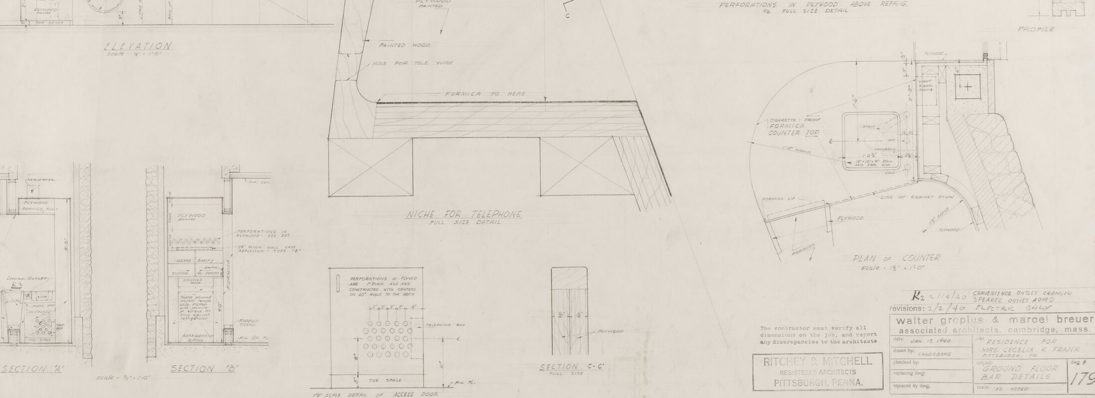
The title block in the lower-right corner lists the architects involved – Walter Gropius & Marcel Breuer, with additional contributions from Ritchey & Mitchell, also specifying that the drawing is associated with Pittsburgh, Pennsylvania. The drawing is scaled at 1’-0” = 1’ and 1 1/2”=1’0” and is intended for actual size representation and construction details. There are signatures for authorization and notes for checking revisions, indicating this is a formal and official document intended for a construction project.
This detailed and technical drawing combines various architectural visualization methods to illustrate the precise dimensions, structure, and construction techniques required for a specific architectural element or system.
Anthropic Claude
Created by us.anthropic.claude-3-5-sonnet-20241022-v2:0 on 2025-06-25
This appears to be an architectural drawing or blueprint showing various technical details and specifications. The drawing includes multiple views: plan views, elevations, and sections labeled as "SECTION X" and "SECTION Y." There are detailed measurements and annotations throughout the drawing. The layout suggests this might be for some kind of commercial or institutional building project. The drawing style is typical of professional architectural documentation, with clean lines and precise measurements. In the bottom right corner, there appears to be a title block with project information, though the text is not clearly legible in this image. The drawing includes curved elements and what appear to be structural details for walls or partitions.
Created by claude-3-haiku-20240307 on 2024-12-31
The image appears to be a detailed engineering or architectural drawing, containing various technical diagrams, cross-sections, and schematics. It seems to depict the plans or specifications for a complex structure or machinery. The drawing includes various annotations, measurements, and technical details, suggesting it is a working document used in the design or construction process. Overall, the image presents a highly detailed technical illustration, without any visible human subjects.
Created by claude-3-opus-20240229 on 2024-12-31
The image shows various architectural drawings and diagrams, likely blueprints or plans for constructing some kind of building or structure. There are detailed sketches showing different views and cross-sections, with measurements and technical annotations. The drawings include floor plans depicting the layout of rooms and spaces, as well as more detailed zoomed-in sections highlighting specific architectural features and design elements. The sketches have a precise, engineering-style appearance typical of architectural plans used to map out and specify the design of a building project prior to construction.
Created by claude-3-5-sonnet-20241022 on 2024-12-31
This appears to be an architectural drawing or blueprint showing various technical details and specifications. The image contains multiple views including plans, elevations, and sections of what seems to be a building or structure. The drawing includes detailed measurements and notations, and appears to be professionally drafted. In the bottom right corner, there's text indicating this is related to a project in Pittsburgh, PA. The drawing shows various architectural elements including curved surfaces, columns, and detailed construction specifications. The layout suggests this is a working document used for construction or renovation purposes.
Meta Llama
Created by us.meta.llama3-2-11b-instruct-v1:0 on 2025-03-16
The image presents a detailed technical drawing of a building, showcasing its various sections and components. The drawing is rendered in black ink on white paper, with a large central section featuring a curved roof and a prominent chimney. The surrounding areas are filled with smaller drawings, diagrams, and text, providing additional information about the building's design and specifications.
Key Features:
- Central Section: A large, curved roof with a prominent chimney.
- Surrounding Sections: Smaller drawings, diagrams, and text providing additional information.
- Design and Specifications: The drawing includes details about the building's layout, materials, and construction methods.
- Technical Details: The drawing is likely intended for use by architects, engineers, or contractors involved in the construction or renovation of the building.
Overall Impression:
The image provides a comprehensive view of the building's design and technical specifications, making it an essential tool for professionals involved in its construction or renovation. The level of detail and precision in the drawing suggests that it was created by a skilled draftsman or architect.
Created by us.meta.llama3-2-90b-instruct-v1:0 on 2025-03-16
The image presents a detailed architectural drawing of a building's design, showcasing various sections and elevations. The drawing is rendered in black ink on a white background, with a mix of handwritten notes and printed text.
Key Features:
- Sections and Elevations: The drawing includes multiple sections and elevations of the building, providing a comprehensive view of its design.
- Handwritten Notes: Handwritten notes are scattered throughout the drawing, offering additional information about the design elements.
- Printed Text: Printed text is used to label different parts of the drawing, such as the title block and section labels.
- Title Block: The title block is located in the bottom-right corner of the drawing and contains information about the project, including the architect's name, date, and location.
- Scale and Units: The drawing includes a scale and units, allowing viewers to accurately measure and understand the design.
Overall Impression:
The image provides a detailed and informative look at the architectural design of a building. The use of both handwritten and printed text adds a personal touch to the drawing, while the inclusion of a title block and scale ensures that the design is accurately represented.
Amazon Nova
Created by amazon.nova-lite-v1:0 on 2025-02-27
The image appears to be a technical drawing or blueprint of a structure, possibly a building or a facility. The drawing is divided into multiple sections, each with different views and details. The drawing includes plans, elevations, and sections of the structure, providing a comprehensive view of its design and layout.
The drawing shows a curved, arched structure with a central opening or entrance. The structure appears to be made of concrete or a similar material, with a smooth, curved surface. The drawing includes measurements and annotations, indicating the dimensions and specifications of the structure.
The drawing also includes details of the interior layout, including the placement of counters, telephone booths, and other elements. The drawing is labeled with the names of the architects and engineers involved in the design, as well as the location of the project.
Overall, the image provides a detailed and technical view of the structure, showcasing its design and layout in a clear and precise manner. The drawing is likely used for construction or engineering purposes, providing the necessary information for the building or facility to be constructed accurately and efficiently.
Created by amazon.nova-pro-v1:0 on 2025-02-27
The image is a blueprint of a building. The blueprint is divided into several sections, each showing different aspects of the building's design. The top section shows the building's exterior, with a curved roof and a rectangular structure. The middle section shows the building's interior, with a staircase and a small room. The bottom section shows the building's foundation and the surrounding area. The blueprint also includes measurements and notes.
Google Gemini
Created by gemini-2.0-flash on 2025-05-27
The image is a black and white blueprint. It contains different architectural plans, elevations and sections for a building's interior design, specifically focusing on a niche for a telephone and a counter area. The overall design appears to be modern, with clean lines and geometric shapes.
The blueprint is detailed, with various annotations and measurements included. Terms like "ELEVATION," "SECTION," "PLAN OF COUNTER," and "NICHE FOR TELEPHONE" are clearly labeled, indicating different aspects of the design. It also lists the architects and associated information, including "Walter Gropius & Marcel Breuer, associated architects, Cambridge, Mass." and "Ritchie & Mitchell, Architects, Pittsburgh, Penna." The date is listed as "Jan. 5, 1944."
Created by gemini-2.0-flash-lite on 2025-05-27
This is an architectural blueprint, likely for a building or structure. It contains several different views and details:
- Plan: A top-down view of a curved section of the building's upper portion, showing its shape and some internal elements.
- Elevation: A side view, possibly of a wall or structure, showing its vertical dimensions, openings (like windows or doors), and any decorative features.
- Sections: Detail views that cut through the structure to show the composition of the walls, floors, and other parts. There are multiple sections labelled "Section A" and "Section B"
- Details: Specific areas are enlarged to display features. Includes a "Niche for Telephone" details.
- Plan of a Counter: A detailed plan view of the counter
- Measurements and Labels: The drawing contains dimensions, and labels the parts of the design.
It's a highly technical drawing, filled with lines, symbols, and annotations, that guides construction. The title on the lower right says "Ground Floor Detail"
Mistral Pixtral
Created by us.mistral.pixtral-large-2502-v1:0 on 2025-05-31
The image is a detailed architectural drawing, likely a floor plan and elevation of a building. Here is a breakdown of its components:
Main Plan View:
- The central part of the drawing shows a large, semi-circular structure with various rooms and sections labeled.
- The structure appears to have a main entrance and several smaller rooms or sections branching off from the central area.
- There are annotations and measurements indicating dimensions and specific features of the building.
Sections:
- There are several cross-sectional views labeled "Section A-A," "Section B-B," and "Section C-C." These sections provide detailed internal views of the building at different points.
- Each section shows the layout of walls, floors, and other structural elements, including stairs, doorways, and possibly mechanical or electrical components.
Elevations:
- There are elevation views that show the side profiles of the building. These views include details of the roof, windows, and other external features.
- The elevations help to understand the height and external appearance of the structure.
Details and Annotations:
- The drawing includes various annotations and labels that provide additional information about the materials, dimensions, and specific features of the building.
- There is a legend or key in the bottom right corner that likely explains the symbols and abbreviations used in the drawing.
Title Block:
- The bottom right corner contains a title block with information about the project, including the name of the architect or designer, the date, and possibly the client or location.
- The title block also includes a scale and other technical details relevant to the drawing.
Overall, the image is a comprehensive architectural plan that provides a detailed overview of a building's layout, structure, and design elements.
Qwen
Created by Qwen/Qwen2.5-VL-7B-Instruct on 2025-07-20
The image is a technical drawing or blueprint, likely of a design for a bar or counter area. The drawing includes several views and details:
Plan View (Top Left): This shows the overall layout of the bar area with dimensions and labels for various features such as the telephone box, sink, and other elements. The plan is scaled at 1/2" = 1'-0".
Elevation View (Bottom Left): This side view illustrates the depth and construction details of the bar counter. It includes specifications for materials like formica and plywood, as well as dimensions and notes on the construction process.
Sections (Bottom Center): Several cross-sectional views labeled as "Section A," "Section B," and "Section C-C" provide detailed information about cross-sections of the bar, including perforations, recesses, and the placement of the telephone niche.
Profile View (Right Center): This vertical view shows the profile of the bar counter, including the perforations in the plywood above the refrigerator and the dimensions of the perforations.
Plan of Counter (Bottom Right): Another top-down view of the counter area, providing additional details about the construction and placement of the counter top and other elements.
The drawing is meticulous and includes annotations, scales, and dimensions, indicating that it is a detailed architectural or engineering drawing intended for construction or manufacturing purposes. The footer of the drawing includes the names of the architects, the project name, and the date, along with other technical information.
Created by Qwen/Qwen2.5-VL-72B-Instruct on 2025-07-20
This image is a detailed architectural blueprint or construction drawing for a bar area within a residence designed by Walter Gropius and Marcel Breuer. The drawing includes various sections and elevations, providing a comprehensive view of the bar's design and construction details.
Key Elements of the Drawing:
Plan View:
- The plan view shows the layout of the bar area, including the counter, storage, and other features.
- Annotations indicate materials such as plywood and Formica, and details like a cigarette-proof Formica top and a Formica lip.
Elevation View:
- The elevation view provides a side perspective of the bar, showing the height and depth of the counter, shelves, and other elements.
- It includes details such as a niche for a telephone and perforations in plywood above the refrigerator.
Sections:
- Section A-A: Shows a detailed view of a niche, likely for storage or a small appliance.
- Section B-B: Provides a cross-section of the bar counter, showing the layers of materials used.
- Section C-C: Focuses on the access door, detailing the construction and materials.
Profile View:
- The profile view shows the shape and dimensions of the perforations in the plywood above the refrigerator.
Material Specifications:
- The drawing includes notes on materials such as plywood, Formica, and painted wood, along with specific dimensions and installation details.
Revisions and Notes:
- The bottom right corner contains information about the project, including the date (January 17, 1940), revisions made, and the names of the architects and associated firms.
- It is for a residence for Mrs. Cecelia K. Frank in Pittsburgh, PA, and is titled "Ground Floor Bar Details."
Purpose:
This blueprint serves as a guide for the construction of the bar area, providing all necessary details for builders and contractors to accurately construct the space as designed by the architects.
Text analysis
Amazon