
Machine Generated Data
Tags
Color Analysis
Feature analysis
Amazon
Clarifai
AWS Rekognition
| Rug | 56.3% | |

Categories
Imagga
created on 2018-03-22
| text visuals | 100% | |
Captions
Microsoft
created by unknown on 2018-03-22
| a close up of text on a white surface | 55.9% | |
| a close up of text on a white background | 55% | |
| close up of text on a white surface | 50.4% | |
Clarifai
No captions written
Salesforce
Created by general-english-image-caption-blip on 2025-05-02
a photograph of a drawing of a plan for a house
Created by general-english-image-caption-blip-2 on 2025-06-27
a drawing of a plan for a building
OpenAI GPT
Created by gpt-4 on 2025-03-05
This image displays a technical drawing or blueprint. It appears to be an architectural or engineering plan, showing a variety of detailed cross-sectional views and elevations. The drawing includes precise lines, measurements, and notations indicating the dimensions and construction details for specific components of a structure.
There are alphanumeric codes and references, which typically correlate to specific materials or parts to be used in the construction process. Based on the professionalism and detail of the drawing, it was likely used for constructing a building or a part of a building, detailing how various elements should be built and assembled.
The paper appears aged and has fold marks, creases, and some discolorations, suggesting that it is an original drawing that has been used or stored for some time. The title block in the lower right corner usually contains information such as the project name, the names of the architects or engineers, the company they work for, the date, the scale of the drawing, and the drawing number, but that specific information cannot be provided here.
Created by gpt-4o-2024-05-13 on 2025-03-05
The image depicts an architectural blueprint. It includes detailed technical drawings and specifications for a construction project. The blueprint is labeled with various measurements, annotations, and cross-sections that outline different parts of the design. In the bottom right corner of the blueprint, there is a title block that contains information about the project, including the architects (Walter Gropius and Marcel Breuer), the architectural firm (Ritchey & Mitchell), the location (Pittsburgh, Pennsylvania), and detail references. The blueprint appears to be a floor plan and includes a scale, revision dates, and other technical details necessary for building construction or architectural planning.
Anthropic Claude
Created by us.anthropic.claude-3-5-sonnet-20241022-v2:0 on 2025-06-24
This image appears to be an architectural floor plan or technical drawing. It's a detailed blueprint with various room layouts, dimensions, and structural elements drawn in a professional drafting style. The drawing is primarily in black lines on a white background and appears to be somewhat aged or vintage, as indicated by slight discoloration around the edges. At the bottom of the drawing, there's a title block which appears to be from Pittsburgh, Pennsylvania. The plan shows various spaces with walls, doorways, and other architectural elements carefully laid out and dimensioned. The drawing has a technical, precise quality typical of professional architectural documentation.
Created by claude-3-haiku-20240307 on 2024-12-29
The image appears to be a detailed engineering or architectural blueprint or technical drawing. It contains various geometric shapes, lines, dimensions, and annotations, suggesting it is a set of technical specifications or schematics for a design or structure. The drawing appears to be hand-drawn or drafted, with a vintage or aged appearance. There are no human faces or identifiable individuals visible in the image.
Created by claude-3-opus-20240229 on 2024-12-29
This image shows an architectural blueprint or floor plan sketch. It depicts the layout and dimensions of what appears to be a residential building or house. The plan includes measurements, room labels, and other technical details drawn using precise lines and markings. The blueprint is rendered on an aged or yellowed paper background, giving it a vintage or historical aesthetic.
Created by claude-3-5-sonnet-20241022 on 2024-12-29
This appears to be an architectural drawing or blueprint, showing various technical details and floor plans. The drawing appears to be from a project in Pittsburgh, Pennsylvania, as indicated in the title block at the bottom right corner. It contains detailed measurements, lines, and annotations typical of architectural drawings. The layout shows cross-sections and elevations of what seems to be part of a building design, with various structural elements and dimensions clearly marked. The drawing is primarily in black and white, with thin lines on what appears to be paper that has aged slightly. There's also what looks like a small piece of yellowed tape or adhesive visible at the edge of the document.
Meta Llama
Created by us.meta.llama3-2-11b-instruct-v1:0 on 2025-03-11
The image presents a detailed floor plan, likely for a building or structure, featuring various rooms and spaces. The plan is drawn in pencil on a large sheet of paper, with measurements and notes written in the margins.
Key Features:
- Rooms and Spaces: The floor plan includes several rooms and spaces, including a living room, kitchen, bedrooms, bathrooms, and possibly a dining room or office.
- Measurements and Notes: The plan includes measurements and notes in the margins, providing additional information about the design and layout of the space.
- Pencil Drawing: The floor plan is drawn in pencil, which suggests that it may be a rough or preliminary design.
- Large Sheet of Paper: The plan is drawn on a large sheet of paper, which indicates that it may be a detailed or comprehensive design.
- Ritchev & Mitchell: The plan includes the name "Ritchev & Mitchell" in the bottom-left corner, which suggests that it may be a design or architectural firm.
- Pittsburgh, Penna.: The plan also includes the location "Pittsburgh, Penna." in the bottom-left corner, which suggests that it may be a design or architectural firm based in Pittsburgh, Pennsylvania.
- Walter Grothus & Marce Breuer: The plan includes the name "Walter Grothus & Marce Breuer" in the bottom-right corner, which suggests that it may be a design or architectural firm.
- Date: The plan includes a date, "3/27/49," in the top-right corner, which suggests that it may be a design or architectural firm based in Pittsburgh, Pennsylvania.
Overall:
The image presents a detailed floor plan, likely for a building or structure, featuring various rooms and spaces. The plan is drawn in pencil on a large sheet of paper, with measurements and notes written in the margins. The plan includes the names of several design or architectural firms, including Ritchev & Mitchell and Walter Grothus & Marce Breuer, and suggests that it may be a design or architectural firm based in Pittsburgh, Pennsylvania.
Created by us.meta.llama3-2-90b-instruct-v1:0 on 2025-03-11
The image presents a detailed architectural blueprint, showcasing the intricate design of a building's floor plan. The blueprint is rendered in black ink on a white background, with various lines and symbols that convey the layout and features of the structure.
Key Features:
- Floor Plan: The central focus of the blueprint is the floor plan, which outlines the rooms, corridors, and other spaces within the building.
- Symbols and Notations: Throughout the blueprint, various symbols and notations are used to indicate specific features, such as doors, windows, and electrical outlets.
- Scale and Measurements: The blueprint includes a scale and measurements, allowing architects and builders to accurately interpret the design and construct the building accordingly.
- Architectural Details: The blueprint provides detailed information about the building's architecture, including the location of walls, columns, and other structural elements.
- Room Labels: Each room is labeled with a unique identifier, making it easy to reference specific areas of the building.
- Corridor Layout: The blueprint shows the layout of the corridors, including the location of doors, windows, and other features.
- Electrical and Plumbing: The blueprint includes details about the electrical and plumbing systems, including the location of outlets, switches, and pipes.
Overall Impression:
The blueprint presents a comprehensive and detailed design for a building, showcasing the architect's vision and attention to detail. The use of symbols, notations, and measurements ensures that the design can be accurately interpreted and constructed, resulting in a functional and aesthetically pleasing building.
Amazon Nova
Created by amazon.nova-lite-v1:0 on 2025-01-11
The image shows a blueprint or architectural drawing of a building. The drawing is on a white sheet of paper and contains various lines, shapes, and labels that represent different elements of the building's design. The drawing includes a floor plan, which shows the layout of the rooms and spaces within the building, as well as dimensions, annotations, and other details that provide information about the building's structure and features. The drawing appears to be a technical document used by architects, engineers, or contractors to plan and construct the building.
Created by amazon.nova-pro-v1:0 on 2025-01-11
The image is a blueprint of a building's architectural design. It is a large-scale drawing on a white background with black lines and text. The blueprint includes various sections and elevations of the building, showcasing its layout, dimensions, and structural details. The drawing is divided into multiple sections, each labeled with a number and a description. The sections include floor plans, elevations, and details of specific areas such as windows, doors, and structural elements. The blueprint also includes a title block with information about the project, including the architect's name, the date, and the project's name.
Google Gemini
Created by gemini-2.0-flash on 2025-05-12
Here is a description of the image:
The image shows a detailed architectural drawing on what appears to be a large sheet of paper, likely a blueprint. The paper has a slightly aged appearance, with some yellowing and areas where tape or adhesives have been used.
The drawing itself is intricate and technical, featuring numerous lines, shapes, and labels. It seems to depict various sections and details of a building or structure. There are different sections identified as "SECTION A-A" and "SECTION E-E". There are various notes and measurements written around the drawing, indicating specific dimensions and materials.
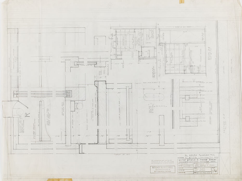
In the bottom right corner, there's text stating "Re 3/27/40 Fluorescent Fixture. Walter Gropius & Marcel Breuer associated architects, Cambridge, Mass." and "RESIDENCE FOR J. KRAUS." The architectural firm is identified as "RITCHEY & MITCHELL, PITTSBURGH, PENNA." and drawing number "174".
The overall impression is that this is an original, hand-drawn architectural plan from the mid-20th century, filled with technical information and details necessary for construction.
Created by gemini-2.0-flash-lite on 2025-05-12
This is an architectural blueprint, likely a drawing of a building's interior or specific architectural details. It is a technical drawing with precise lines, dimensions, and annotations. The blueprint is on a large piece of paper, showing different sections of the planned structure, with multiple views that include floor plans, section views and elevations. It's a document from the archives of "RITCHEY & MITCHELL" and pertains to the design for the "RESIDENCE FOR FORSTER CRACK." It is also labeled as a "FLOURESCENT FIXTURES" plan, dated March 27, 1940, with the names "weiter graplus & marcel breuer" as the architects associated with the project in Cambridge, Massachusetts. The blueprint appears to be an original document, given the aged paper and annotations.
Mistral Pixtral
Created by us.mistral.pixtral-large-2502-v1:0 on 2025-05-23
The image shows a detailed architectural blueprint or technical drawing. It appears to be a floor plan or layout of a building, likely an industrial or commercial structure, given the complexity and specificity of the design elements. Here are some key features and observations:
Layout and Sections:
- The drawing is divided into multiple sections, each labeled with different components and areas.
- There are various rooms and spaces depicted, with walls, doors, and other structural elements clearly marked.
Annotations and Labels:
- The blueprint includes numerous annotations and labels, which provide specific details about different parts of the structure.
- These annotations likely include dimensions, material specifications, and other technical information necessary for construction or renovation.
Scale and Measurements:
- The drawing includes a scale, which is essential for understanding the actual sizes of the depicted elements.
- Measurements are provided for various components, ensuring accuracy in construction.
Date and Identification:
- The blueprint is dated "RC 3/27/50," indicating it was created or revised on March 27, 1950.
- There are stamps and signatures from the architectural firm and possibly the client or contractor, indicating approval or authentication.
Firm Information:
- The architectural firm responsible for the drawing is identified as "WILLIAM GORDON & MARION BYBURT, ARCHITECTS, CAMBRIDGE, MASS."
- There is also a mention of "RITCHEY & DUCHENE, PITTSBURGH, PENNA," which could be the client or another involved party.
Technical Details:
- The drawing includes intricate details such as piping, electrical systems, and possibly HVAC (heating, ventilation, and air conditioning) layouts.
- These details are crucial for ensuring the proper functioning of the building's systems.
Overall, the image is a comprehensive technical drawing used for the design and construction of a building, providing detailed information necessary for accurate implementation.
Qwen
No captions written
Text analysis
Amazon


