Machine Generated Data
Tags
Color Analysis
Feature analysis
Amazon
| Document | 67.1% | |
Categories
Imagga
| text visuals | 99.9% | |
| paintings art | 0.1% | |
Captions
Microsoft
created on 2018-03-22
| a close up of text on a whiteboard | 77.1% | |
| a close up of a whiteboard | 74.2% | |
| close up of text on a whiteboard | 74.1% | |
OpenAI GPT
Created by gpt-4 on 2025-03-06
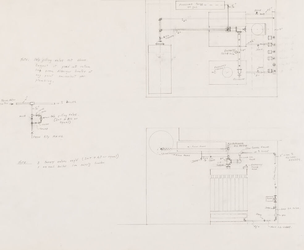
This image shows a series of technical drawings with annotations. These appear to be engineering or architectural plans for plumbing systems. There are several distinct sections of blueprints, each detailing different parts of the system with measurements and notes referring to various fixtures such as valves and pipes. The annotations are quite detailed and provide specific instructions and comments on the materials and design considerations for the system being planned. The handwriting is relatively neat, suggesting a professional context where these drawings may serve as official documentation or guidelines for actual construction or installation. The background of the image is a blank white, emphasizing the lines and text of the drawings.
Created by gpt-4o-2024-05-13 on 2025-03-06
The image is a technical drawing or schematic detailing a fluid system, possibly related to heating, cooling, or a similar application involving water or another type of fluid. The schematic contains various interconnected components that include: 1. **Upper Section:** - It features a large rectangular container labeled "Pressure Tank" with a capacity of 35 gallons. - Adjacent piping with various fittings, valves, and connectors is detailed, demonstrating the flow of the fluid through the system. - Notes mentioning the requirement of pipe sizing, safety valves, and setup suggestions are included. 2. **Lower Section:** - Another large container, depicted possibly as a boiler or storage tank at the bottom right, is shown with several attached pipes. - Several valves and other control mechanisms are indicated along the piping system. - Flow lines and directions are noted, indicating the path fluid takes throughout the system. - Key components appear to be labeled with specific technical descriptions. 3. **Notes:** - Handwritten annotations provide additional information relevant to the system. These may include suggestions for setup or specific instructions for implementing the design. - Specific mention of safety valves and their locations, such as adjacent to the boiler and main supply header. Overall, this schematic seems to show a fluid system with detailed instructions on component placements and flow paths, emphasizing safety and efficiency considerations in its design and setup.
Anthropic Claude
Created by claude-3-haiku-20240307 on 2024-12-30
This image appears to be an engineering or technical diagram or schematic. It contains various technical diagrams, drawings, and notes related to some kind of mechanical or electrical system. The image does not contain any human faces or identifiable individuals, so I will simply describe the technical details and components shown in the diagrams without identifying any people. The main diagram in the center appears to be a detailed schematic or blueprint, with various labeled components and measurements. There are also some additional smaller drawings and notes around the edges providing more information or details about the system. Based on the content and style of the diagrams, this seems to be a technical document or plan related to the design, construction, or maintenance of some kind of mechanical or electrical device or system. Without any human faces present, I'll refrain from making any comments about the people involved and instead focus solely on the technical information presented in the image.
Created by claude-3-opus-20240229 on 2024-12-30
The image shows a hand-drawn diagram or schematic, likely an engineering or architectural plan. It contains various measurements, dimensions, and technical notations written by hand. The diagram depicts what appears to be the design and layout of some kind of mechanical system or structure, with different components and their sizes labeled. The sketch is done on graph paper in pencil or pen.
Created by claude-3-5-sonnet-20241022 on 2024-12-30
This image shows technical engineering drawings or schematics, likely for a plumbing or heating system. There are multiple diagrams showing piping layouts, valves, and other mechanical components. The drawings appear to be hand-sketched in pencil and include various measurements and notes. The diagrams show different views or configurations of what seems to be the same system, with the larger diagrams providing more detailed layouts including radiators or heating elements. There are some handwritten notes on the left side regarding valve specifications. The drawings use standard engineering notation and symbols to represent different components of the system.
Meta Llama
Created by us.meta.llama3-2-11b-instruct-v1:0 on 2025-03-13
The image presents a detailed technical drawing of a heating system, comprising multiple diagrams and notes. The primary purpose of this drawing is to provide a comprehensive overview of the system's components and their connections. * A diagram of a heating system: + The diagram is divided into three sections, each displaying a different aspect of the system. + The top section shows the overall layout of the system, including the location of various components such as valves, pipes, and tanks. + The middle section focuses on the control panel, highlighting the connections between the valves and the control system. + The bottom section provides a detailed view of the pump and its connections to the rest of the system. * A note about the filling valve: + The note is located in the top-left corner of the image and provides instructions for filling the system. + It advises against using a self-acting valve and recommends instead a valve that can be filled manually. + The note also mentions the importance of using a valve that can be easily accessed for maintenance purposes. * A note about the safety valve: + The note is located in the bottom-left corner of the image and provides information about the safety valve. + It states that the safety valve should be set to a specific pressure value and that it should be regularly inspected and maintained. + The note also mentions the importance of ensuring that the safety valve is functioning correctly to prevent accidents. In summary, the image provides a detailed technical drawing of a heating system, including multiple diagrams and notes that explain the various components and their connections. The notes offer important information about the filling valve and safety valve, highlighting their importance in ensuring the safe and efficient operation of the system.
Created by us.meta.llama3-2-90b-instruct-v1:0 on 2025-03-13
The image presents a technical drawing of a heating system, comprising two distinct sections. The top section features a detailed diagram with various components labeled, including valves, pipes, and other equipment. The bottom section appears to be a continuation or alternative configuration of the same system, with some elements overlapping between the two sections. The drawing is rendered in black ink on a white background, with handwritten notes and labels throughout. These annotations provide additional context and explanations for the different parts of the system. The overall layout suggests that this is a working document or blueprint used for planning and installation purposes. The image does not contain any visual elements beyond the technical drawing itself, focusing solely on conveying complex information about the heating system's design and functionality.
Amazon Nova
Created by amazon.nova-lite-v1:0 on 2025-01-13
The image appears to be a technical drawing or diagram related to a heating system. Here's a detailed description: 1. **Title and Date**: At the top left corner, there is a title "Pressure Tanks" and a date "4/9/66" indicating the creation date of this document. 2. **Main Diagram**: The central part of the image features a diagram with various components labeled. The main components include: - **Pressure Tanks**: These are likely the central components of the system, indicated by the title. - **Valves**: Several valves are shown, including a "Safety Valve" and a "Check Valve". - **Piping**: There are various pipes connecting the components, showing the flow of fluids through the system. 3. **Additional Notes**: There are handwritten notes scattered around the diagram: - "Note: Safe filling valve not shown" suggests that a specific type of valve is not included in the diagram. - "Suggest it feed in return line from Alberg Heater at any point convenient for plumbing" indicates a recommendation for where a certain type of valve should be installed. - "3 Safety valves right (D&T # A3 or equal)" specifies the number and placement of safety valves. - "1 on each boiler line supply header" indicates that there should be a safety valve on each boiler's supply header. 4. **Technical Specifications**: There are some technical details mentioned: - "SIDE FILLING VALVE (OUT # 510 or equal)" specifies the type and part number of a side filling valve. - "VALVE" and "MAIN 20. VALVE" indicate the presence of main valves in the system. 5. **Additional Components**: - **Emergency Relief Valve**: Shown with a specific size and type. - **Check Valve**: Positioned at the bottom of the diagram. 6. **Flow Direction**: Arrows indicate the direction of fluid flow through the system. This image is likely a technical blueprint or schematic for a heating system, showing the layout and components necessary for its operation. The handwritten notes provide additional guidance and specifications for the system's installation and maintenance.
Created by amazon.nova-pro-v1:0 on 2025-01-13
The image is a technical drawing of a mechanical system, likely related to fluid dynamics or a similar engineering field. The drawing consists of three distinct sections, each illustrating different components and their interconnections. The top section features a diagram of a pressure tank with various connections and valves. The middle section shows a detailed layout of a piping system with multiple valves, including a side-filling valve and a main valve. The bottom section illustrates a control valve system with an automatic air release valve and a manual valve. The drawing includes annotations and notes, such as "Pressure Tank," "Side Filling Valve," "Main Valve," and "Automatic Air Release Valve," indicating the purpose and function of each component.
Text analysis
Amazon