Machine Generated Data
Tags
Color Analysis
Feature analysis
Amazon
Clarifai

Clarifai
Whiteboard | 63.2% | |
Categories
Imagga
created on 2018-03-22
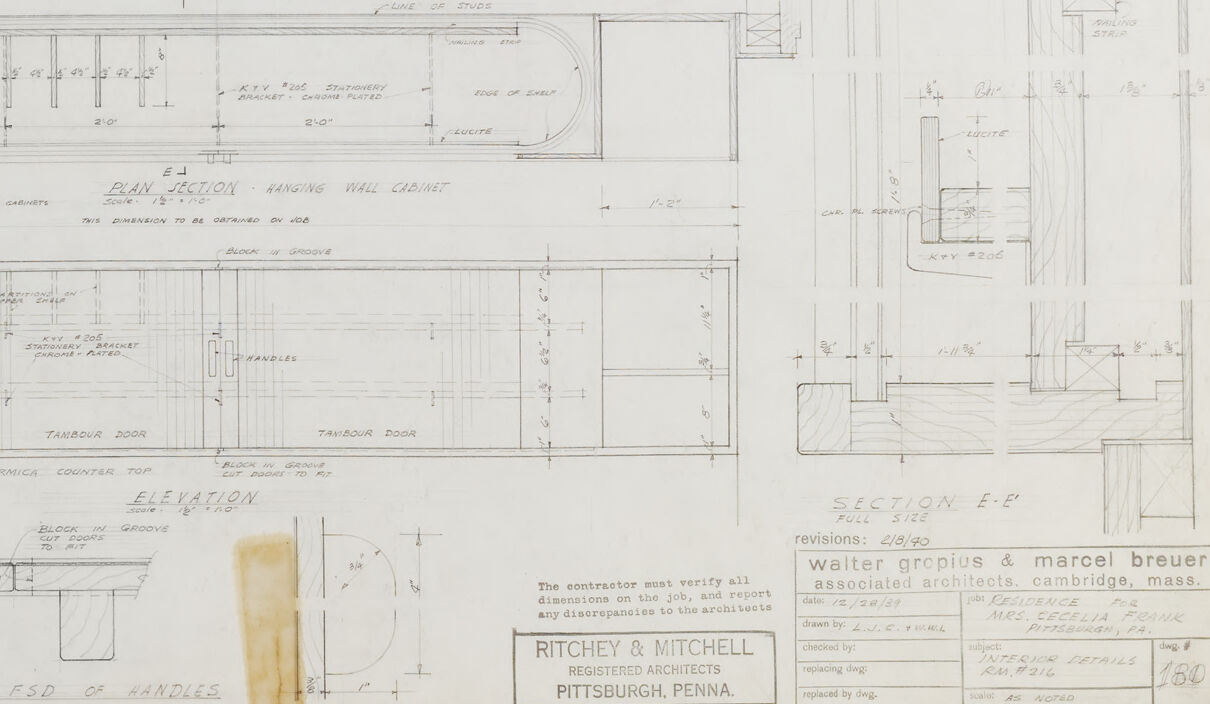
text visuals | 99.8% | |
paintings art | 0.2% | |
Captions
Microsoft
created by unknown on 2018-03-22
a close up of text on a whiteboard | 67.1% | |
a close up of a whiteboard | 66.8% | |
a whiteboard with writing on them | 66.4% | |
Clarifai
No captions written
Salesforce
Created by general-english-image-caption-blip on 2025-05-11
a photograph of a drawing of a plan for a kitchen
Created by general-english-image-caption-blip-2 on 2025-06-28
a drawing of a kitchen and bathroom with plans
OpenAI GPT
Created by gpt-4 on 2025-03-07
This image is a technical drawing or architectural plan. It consists of various diagrams and sections that detail the elements of a particular structure or architectural feature. The drawing includes a combination of floor plans, sections, and elevations, along with detailed notes and dimensions. The annotations are made with precision and include measurements, indicating the exact sizing and placement of components.
The level of detail suggests that this drawing is meant for construction or architectural purposes, as engineers or builders would use this information to construct or understand the specifics of the building or object being portrayed. The plans feature technical notation, such as "SCALE: 1/2" = 1'-0"" (indicating the scale used for the drawing), as well as references to materials and construction methods.
The drawing appears to be quite old given its coloration and the style of the drafting. There may be some discoloration or damage, as indicated by the stains and the wrinkled condition on the paper, which suggests that the document has seen significant use or has been stored for a long period.
There's text mentioning the names Gropius & Breuer - Walter Gropius and Marcel Breuer, who are well-known figures in the modernist architecture movement. This could imply that the architectural plans are associated with their work. The additional text states "RITCHEY & MITCHELL / PITTSBURGH, PENNA", potentially indicating either the drafting firm or the project's location.
Created by gpt-4o-2024-05-13 on 2025-03-07
The image shows a technical architectural blueprint, which includes detailed construction plans for specific sections of a building. The blueprint features multiple diagrams that display various views and cross-sections of the structure, showing floor plans, elevation views, and detailed sectional drawings.
Key elements visible on the blueprint include:
- Floor plans with labeled rooms and dimensions, showing the layout and positioning of structural elements like walls, doors, and fixtures.
- Elevation views, giving a side perspective of the structure, detailing heights and external features.
- Cross-sections, providing a cut-through view of the building, highlighting internal components such as wall structures, foundation details, and built-in features.
- Annotations and labels, indicating measurements, materials, and specific construction notes essential for builders and contractors.
- A title block in the bottom right corner, which provides information about the architectural firm (Ritchey & Mitchell), location (Pittsburgh, Penna), and associated architects (Walter Gropius & Marcel Breuer).
Overall, the blueprint serves as a comprehensive guide for the construction and assembly of the architectural project, ensuring accuracy and uniformity during the building process.
Anthropic Claude
Created by us.anthropic.claude-3-5-sonnet-20241022-v2:0 on 2025-06-25
This image appears to be an architectural drawing or technical blueprint showing various elevations and sections of what seems to be an interior design project. The drawing includes multiple detailed views from different angles, with precise measurements and annotations. The document appears to be from Ritchey & Mitchell of Pittsburgh, Pennsylvania, and includes work related to Walter Gropius and Marcel Breuer. The drawings show various wall sections, floor plans, and detailed specifications for what might be built-in furniture or interior fixtures. The plans are drawn in a professional architectural style with clean lines and technical notations typical of mid-century architectural documentation.
Created by claude-3-haiku-20240307 on 2024-12-29
The image appears to be an architectural or engineering drawing or blueprint. It contains various detailed technical drawings, diagrams, and dimensions, likely for the construction or design of some kind of structure or system. The drawings include floor plans, elevations, and various other schematics and annotations. The overall impression is of a complex, technical document used for the planning and development of a specific project.
Created by claude-3-opus-20240229 on 2024-12-29
The image shows a detailed architectural blueprint or plan for a building, likely a house based on the room labels. It includes precise measurements, dimensions, and annotations for various rooms and structural elements such as walls, doors, windows, cabinets, sinks, and appliances.
The blueprint contains floor plans, elevations, and cross-sections to comprehensively depict the layout and construction of the building. Rooms like a kitchen, dining room, and bedrooms are called out.
The plans are hand-drawn in pencil or ink on gridded drafting paper. There are some erasure marks and manual revisions visible, suggesting this is an original working drawing used in the design and construction planning process for this building.
At the bottom, a block contains the project title "RITCHEY & MITCHELL Residence", indicating these are the architectural plans for a custom residential home. Overall, it is a very thorough and technically detailed set of architectural drawings.
Created by claude-3-5-sonnet-20241022 on 2024-12-29
This is an architectural drawing or blueprint showing various detailed elevation and section views of what appears to be an interior design project. The drawings are technical in nature, showing multiple angles and views of what could be built-in furniture or cabinetry. The plans include precise measurements and construction notes. The drawing is credited to Ritchey & Mitchell from Pittsburgh, Pennsylvania, and appears to be related to a project involving Walter Gropius and Marcel Breuer. The drawing style is typical of mid-century architectural documentation, with clean lines and detailed annotations. The layout includes both plan and elevation views, giving a comprehensive understanding of the design from different perspectives.
Meta Llama
Created by us.meta.llama3-2-11b-instruct-v1:0 on 2025-03-14
The image presents a detailed architectural blueprint, showcasing various rooms and spaces within a building. The blueprint is divided into sections, each representing a different area of the structure. The rooms are depicted in a two-dimensional format, with lines and symbols used to convey measurements, dimensions, and other important details.
Key Features:
- Room Layouts: The blueprint features several rooms, including a living room, kitchen, dining room, bedrooms, and bathrooms. Each room is carefully designed to optimize space and functionality.
- Measurements and Dimensions: The blueprint includes precise measurements and dimensions for each room, ensuring that the structure is built to exact specifications.
- Architectural Symbols: The blueprint employs a range of architectural symbols to convey specific information, such as door and window locations, electrical outlets, and plumbing fixtures.
- Scale: The blueprint is drawn to scale, allowing architects and builders to accurately interpret the design and make any necessary adjustments during the construction process.
- Materials and Finishes: The blueprint may also include information about the materials and finishes to be used in each room, such as flooring, walls, and ceilings.
Purpose:
The purpose of this blueprint is to provide a comprehensive guide for architects, builders, and contractors to construct the building according to the designer's specifications. It serves as a reference point for ensuring that the final product meets the desired standards of quality and functionality.
Conclusion:
In summary, this blueprint is a detailed and precise representation of the building's design, providing a clear understanding of the layout, measurements, and materials required for its construction. It is an essential tool for architects, builders, and contractors to ensure that the final product meets the desired standards of quality and functionality.
Created by us.meta.llama3-2-90b-instruct-v1:0 on 2025-03-14
The image presents a detailed architectural drawing, likely a blueprint or technical illustration, showcasing the floor plan and elevation of a building. The drawing is rendered in black ink on white paper, with various rooms and features labeled in small text.
Key Features:
- Floor Plan: The floor plan occupies the majority of the image, depicting the layout of the building's interior spaces. It includes several rooms, corridors, and staircases, all carefully measured and labeled.
- Elevation: The elevation section is located at the bottom center of the image, providing a side view of the building's exterior. This section shows the building's height, windows, doors, and other architectural details.
- Labels and Annotations: Throughout the drawing, there are numerous labels and annotations that provide additional information about the building's design and construction. These include notes on materials, dimensions, and other technical specifications.
- Scale and Measurements: The drawing includes a scale bar and various measurements, allowing viewers to understand the building's size and proportions.
- Architectural Style: The building's architectural style appears to be modernist, with clean lines, minimal ornamentation, and an emphasis on functionality.
Overall Impression:
The image presents a meticulous and detailed architectural drawing that showcases the building's design and construction. The use of black ink on white paper creates a clear and legible visual representation, making it easy to understand the building's layout and features. The inclusion of labels, annotations, and measurements adds depth and context to the drawing, providing a comprehensive understanding of the building's design and construction.
Amazon Nova
Created by amazon.nova-lite-v1:0 on 2025-01-10
The image is a detailed architectural drawing, likely a floor plan or blueprint, from the 1960s. It is composed of multiple sections, each illustrating different parts of a building's layout. The drawing is on a white background with black lines and annotations. Each section of the drawing is labeled with specific dimensions and details, such as "18-00-00" and "20-00-00," indicating measurements in feet and inches. The drawing includes various rooms and spaces, with annotations for doors, windows, and structural elements. The overall layout suggests a residential or commercial building, possibly a house or an office space. The drawing is signed by "Walter Gropius & Marcel Breuer," indicating the architects who designed the building. The image also includes a note stating, "The contractor must verify all dimensions on the site," emphasizing the importance of accuracy in construction.
Created by amazon.nova-pro-v1:0 on 2025-01-10
The image is a technical drawing, likely an architectural blueprint, depicting various floor plans and elevations of a building. The blueprint is composed of multiple sections, each representing different views and details of the structure. The drawings are rendered in black ink on a white background, with precise lines and annotations. The blueprint includes detailed floor plans, elevations, and sections, providing a comprehensive view of the building's layout and design. The annotations and dimensions are clearly marked, indicating specific measurements and features of the structure. The overall layout suggests a complex and multi-level building with various rooms, corridors, and structural elements.
Google Gemini
Created by gemini-2.0-flash on 2025-05-08
Here is a description of the image:
This image features a technical drawing, possibly an architectural or engineering blueprint, presented on a large sheet of paper. The paper has a pale, off-white color and exhibits slight creases and wrinkles, suggesting it's been handled or stored. The drawing is densely packed with various diagrams, elevations, sections, and details of a cabinet or furniture piece. Fine lines, labels, and dimensions are precisely rendered, indicating a professional design process. Some handwritten notes are scattered across the drawing, adding to its technical nature.
A small, rectangular stamp or label is located in the lower right corner, containing text in a neat, professional typeface. The words "RITCHEY & MITCHELL" are visible, implying this is the name of the architectural or engineering firm responsible for the drawing. Below this, the text "PITTSBURGH, PENNA" specifies the firm's location. Above the firm's name, it mentions "Waiter greplus & marcel breuer associated architects, camtridge, mass"
Near the bottom of the drawing, a yellowish, semi-transparent tape or sticker covers part of the drawing, obscuring some of the details. This adds to the overall vintage and functional feel of the blueprint.
Created by gemini-2.0-flash-lite on 2025-05-08
This image is a blueprint or architectural drawing. It features multiple views, sections, and elevations of a kitchen layout or cabinetry design. The drawing is detailed, showing various elements like cabinets, countertops, doors, and dimensions. The style of the drawing suggests it may be an older architectural plan, possibly from the mid-20th century. The drawing is labeled with the names "RITCHEY & MITCHELL" as the registered architects from Pittsburgh, Pennsylvania. It also shows the name of "Walter gropius & marcel breuer associated architects" from Cambridge, Mass.
Mistral Pixtral
Created by us.mistral.pixtral-large-2502-v1:0 on 2025-05-29
The image depicts a detailed architectural blueprint, likely for a residential building. It includes various views and sections of the structure, such as floor plans, elevations, and sections. Here's a breakdown of the different parts visible in the blueprint:
Floor Plans:
- Several floor plans are shown, indicating the layout of different levels of the building. These plans include rooms, hallways, staircases, and other architectural features.
- The floor plans are labeled with dimensions and specifications for various elements like walls, doors, and windows.
Elevations:
- Elevations provide views of the building's exterior from different sides. These views show the height and design of the walls, windows, doors, and other external features.
- Detailed measurements and notes are included to specify the dimensions and materials used.
Sections:
- Cross-sections of the building are shown, providing a vertical slice through the structure. These sections illustrate the internal layout, including the arrangement of floors, ceilings, and structural elements.
- Sections help in understanding the spatial relationships and the structural design of the building.
Details:
- Specific details of certain architectural elements are highlighted, such as window designs, door frames, and other structural components.
- These details include precise measurements and notes on construction methods and materials.
Notes and Annotations:
- The blueprint includes various notes and annotations that provide additional information about the design and construction of the building.
- These notes may include specifications for materials, construction techniques, and other relevant details.
Title Block:
- The bottom right corner of the blueprint contains a title block with information about the project, including the names of the architects, the location, and the date.
- The title block also includes a scale and other technical information relevant to the blueprint.
Overall, the blueprint provides a comprehensive set of drawings and details necessary for the construction of the building, ensuring that all aspects of the design are clearly communicated to the builders and contractors.
Qwen
No captions written