Machine Generated Data
Tags
Color Analysis
Feature analysis
Amazon
Clarifai

Clarifai
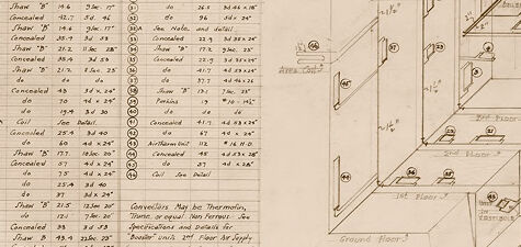
| Envelope | 70.2% | |
Categories
Imagga
created on 2018-03-22
| text visuals | 99.6% | |
| paintings art | 0.4% | |
Captions
Microsoft
created by unknown on 2018-03-22
| a close up of text on a white background | 80.2% | |
| a close up of text on a white surface | 79.1% | |
| a close up of text on a black background | 74.4% | |
Clarifai
No captions written
Salesforce
Created by general-english-image-caption-blip-2 on 2025-06-28
a drawing of a building with a diagram of the electrical system
Created by general-english-image-caption-blip on 2025-05-03
a photograph of a drawing of a plan for a building
OpenAI GPT
Created by gpt-4 on 2025-03-06
This image appears to be a technical drawing or architectural plan, done by hand. On the left side of the image, there is a "RADIATOR SCHEDULE" chart with several columns and rows detailing numbers and specifications likely relevant to a building's heating system. Each row lists a radiator number, its size, and other numerical data that could pertain to heat output or dimensions.
On the right side, there's a "Piping Diagram Bird's Eye View" representing a top-down view of a room or building layout, with various numbers and lines indicating the placement and path for pipes, radiators, and other related systems. They are labeled with numbers that probably correspond to those in the radiator schedule.
At the top right corner of the diagram, the floor layout indicates room separations, with arrows showing the direction of the piping system. There's also a note indicating "North."
At the bottom right of the image, there is a descriptive note which reads "DESIGNED FOR McCRUM-WATSON AND LUELLA N. WATSON, GRAPE AND SPENCER STREETS, LOCK HAVEN, PA." followed by a signature and date, suggesting this is a custom heating system design for a specific location in Lock Haven, Pennsylvania.
The handwriting and detailed annotations, along with little corrections and notes, give the impression of a working document used in the planning or installation process for a building's heating system.
Created by gpt-4o-2024-05-13 on 2025-03-06
The image is an architectural drawing, specifically a piping diagram for a heating system in a building. It is a detailed technical drawing that includes a bird's eye view of the system layout.
On the left side of the image, there is a "Radiator Schedule" table, which lists various rooms or areas, identifying each by a number. The table includes columns for the room number, type, floor, size (varied figures in inches), and other specific heating requirements. The schedule ensures that the proper heating components are placed in the appropriate locations within the building.
The right side of the image contains the primary diagram, a three-dimensional sketch, displaying a network of pipes and their connections to radiators throughout what appears to be a multi-story building. This detailed illustration includes labels, measurements, and specific installation notes, indicating the path of the main and branch lines, as well as the placement of the radiators themselves.
Annotations on the drawing include specific installation guidelines, operational instructions, and notes for adjustments to the setup in different scenarios. The image indicates it is for a residence belonging to a Mrs. Adele Levy, designed by Walter Grofeld and Annelle Berliner, Associated Architects and Engineers, Inc. The sheet is numbered "No 1 H" and is dated to a project in Dutchess County, New York, dated September 1926.
Anthropic Claude
Created by us.anthropic.claude-3-5-sonnet-20241022-v2:0 on 2025-06-25
This appears to be an architectural or engineering drawing showing a piping diagram and radiator schedule. On the left side is a detailed table labeled "RADIATOR SCHEDULE" with multiple rows and columns containing specifications and measurements. On the right side is a complex piping layout diagram showing various connections, junctions, and flow paths. The drawing includes numbered reference points and dimensional notations throughout the piping system. The document appears to be a technical blueprint or schematic, likely used for heating system installation or maintenance. The drawing style suggests this is a historical document, possibly hand-drawn, with careful attention to detail and precise measurements included.
Created by claude-3-haiku-20240307 on 2024-12-30
The image appears to be an engineering or technical diagram. It contains a detailed schematic or blueprint-style drawing with various labeled components and measurements. The central part of the image depicts a complex mechanical or electrical system, likely some kind of machinery or equipment. The diagram includes a table or schedule on the left side that provides specifications and details about various "radiator" components. Overall, this image seems to be an engineering or technical reference document containing detailed schematics and specifications for a complex system or device.
Created by claude-3-opus-20240229 on 2024-12-30
The image shows an engineering/architectural drawing or schematic of what appears to be a radiator schedule. The drawing contains precise measurements and dimensions for different radiator components, with labels like "Sections", "Heating Surface Sq. Ft.", "Length over Tapping", etc.
In the top left corner is a table listing various radiator schedule entries, each with specific dimensions and ratings. The main part of the drawing depicts detailed front and side views of a radiator unit, with numerical callouts referencing the dimensions in the table.
The lower part of the drawing contains notes specifying "Burnham 'Pacemaker' Radiation (Without Sleeves)", a model or product name, along with the draftsman's name "Frank Millard" and date "March 15, 1935". It has the overall appearance of a precise mechanical drawing used for manufacturing or installation of this radiator system.
Created by claude-3-5-sonnet-20241022 on 2024-12-30
This image appears to be an architectural or engineering drawing showing a piping diagram and radiator schedule. On the left side, there's a detailed table labeled "RADIATOR SCHEDULE" with multiple rows and columns containing specifications and measurements. On the right side, there's a complex piping layout diagram showing various connections, valves, and flow paths. The drawing includes dimensions and numbered reference points throughout the system. It appears to be a technical document for a heating or cooling system installation, likely for a building's HVAC system. The document appears to be hand-drawn on paper and includes various notes and annotations to guide installation or maintenance.
Meta Llama
Created by us.meta.llama3-2-11b-instruct-v1:0 on 2025-03-12
The image presents a detailed floor plan and radiator schedule for a residence, likely created by an architect or engineer. The floor plan is rendered in black ink on beige paper, showcasing the layout of the residence, including various rooms, doorways, windows, and other architectural features. The radiator schedule, located to the left of the floor plan, lists the type, size, and location of each radiator in the residence, providing essential information for heating and cooling purposes.
Key Features:
- Floor Plan: A detailed drawing of the residence's layout, including rooms, doorways, windows, and other architectural features.
- Radiator Schedule: A list of radiators, including type, size, and location, providing essential information for heating and cooling purposes.
- Beige Paper: The background of the image, which provides a neutral and clean contrast to the black ink used for the drawings.
- Black Ink: The medium used for the drawings, which provides clear and legible lines and details.
- Architectural Details: The image includes various architectural details, such as doorways, windows, and other features, which provide insight into the design and functionality of the residence.
Purpose:
The purpose of the image is to provide a detailed and accurate representation of the residence's layout and heating system, allowing architects, engineers, and builders to understand the design and functionality of the space. The image is likely used as a reference point for construction and renovation projects, ensuring that the final product meets the desired specifications and standards.
Conclusion:
In conclusion, the image presents a detailed floor plan and radiator schedule for a residence, providing essential information for architects, engineers, and builders. The use of black ink on beige paper creates a clear and legible image, while the inclusion of architectural details provides insight into the design and functionality of the space. Overall, the image is a valuable resource for anyone involved in the construction or renovation of the residence.
Created by us.meta.llama3-2-90b-instruct-v1:0 on 2025-03-12
The image depicts a technical drawing of a building's floor plan, accompanied by a radiator schedule. The floor plan is rendered in black ink on a beige background and features various rooms, including a dining room, kitchen, and bedrooms. Each room is labeled with its purpose and dimensions.
On the left side of the image, a radiator schedule is presented in a table format. This schedule outlines the specifications for each radiator, including its type, size, and location within the building. The table also includes columns for notes and comments, allowing for additional information to be recorded.
In the bottom-right corner of the image, a note is written in pencil, which appears to be a reference or instruction related to the project. The overall design of the image suggests that it is a working document, intended for use by architects, engineers, or contractors involved in the construction or renovation of the building.
Amazon Nova
Created by amazon.nova-lite-v1:0 on 2025-01-12
The image is a technical drawing of a floor plan, specifically for the first floor of a building. It includes a radiator schedule on the left side, listing details such as radiator sizes, types, and placements. The main part of the image shows the layout of the floor, including walls, doors, and windows. The drawing is labeled "Bird's Eye View," indicating a top-down perspective. The document also includes notes about the piping and electrical systems, as well as the location of the radiators and other fixtures. The drawing is signed by Walter Gropius and Martha Breuer, indicating that they were the architects responsible for the design.
Created by amazon.nova-pro-v1:0 on 2025-01-12
The image is a blueprint of a building with a radiator schedule, piping diagram, and other details. The radiator schedule lists various types of radiators, their dimensions, and other specifications. The piping diagram shows the layout of the piping system, including the location of the radiators and other components. The blueprint also includes other details such as the location of the windows, doors, and other features of the building.
Google Gemini
Created by gemini-2.0-flash on 2025-04-30
Here is a description of the image:
The image appears to be a vintage architectural drawing or blueprint. It consists of multiple sections with different types of information, all related to the piping and heating system of a residence.
Key elements of the image:
Radiator Schedule: On the left, there is a table titled "RADIATOR SCHEDULE" with columns for "Rad No," "Type," and dimensions. This table lists different radiator types, sizes, and other specifications.
Piping Diagram: The central and primary focus of the image is a diagram labeled "PIPING DIAGRAM - BIRD'S EYE VIEW." This diagram is a schematic representation of the piping system, showing the arrangement of pipes, radiators, and other components throughout the different floors of the building.
Building Floors: The piping diagram displays several floors, labeled "Ground Floor," "1st Floor," "2nd Floor," and "3rd Floor." Each floor has its piping layout depicted, along with the placement of radiators and other heating elements.
Notes and Details: Scattered around the main diagram are various notes and specifications. For instance, one note mentions "Rad. 32-A may be Vulcan Fin Type..." while another refers to "Note: Pool-Hot Water Heater..."
Title and Attribution: At the bottom right corner, there's a title indicating the residence is for "Mrs. Cecelia Frank" in Pittsburgh, PA. It also credits "Walter Gropius and Marcel Breuer Associated Architects" from Cambridge, Mass.
Handwritten Number: In the bottom right corner, there's a handwritten "No 1H," likely indicating this is sheet number one.
In essence, the image is an old architectural document that details the heating system design and layout for a specific residence.
Created by gemini-2.0-flash-lite on 2025-04-30
This is a technical drawing, specifically a piping diagram from a bird's eye view. It outlines the heating system for a residence. The drawing is labeled as "Residence for Mrs. Cecelia Frank, Pittsburg Pa" and was done by Walter Gropius and Marcel Breuer Associates, architects from Cambridge, Mass.
The image is a hand-drawn architectural or engineering diagram, likely dating from the mid-20th century based on the style and the architects. The drawing shows a schematic representation of a building with multiple floors (ground, first, and second). The diagram's focus is on detailing the layout of the heating system.
Here's a breakdown of the key elements:
- Radiator Schedule: A table is present to the left of the main diagram. It lists the different types, sizes, and locations of the radiators within the house. Each radiator is given a number and a specification related to its location, which corresponds to the numbers marked in the piping diagram.
- Piping Layout: The central part of the diagram shows the pipes and their arrangement through the different floors. The pipes are drawn in a three-dimensional perspective to suggest their location within the building, and various symbols indicate the placement of radiators, heating units, and other components. The diagram also shows the flow of pipes connecting different areas of the building.
- Heating System Components: The piping layout indicates the locations of heating-related components such as the boiler, water heater, and circulator.
- Annotations and Notes: Various notes and annotations provide additional information about the materials, dimensions, and specific details of the system. These notes explain the specifications of certain units and the location of components.
The diagram’s purpose is to provide a clear visual representation of the heating system, to assist in construction and maintenance.
Mistral Pixtral
Created by us.mistral.pixtral-large-2502-v1:0 on 2025-05-28
The image is a detailed technical drawing, specifically a piping diagram for a building's heating system. It appears to be a blueprint or architectural plan, likely from the early to mid-20th century, given the style of drafting and annotations.
Key Components of the Drawing:
Radiator Schedule:
- On the left side of the image, there is a table labeled "Radiator Schedule."
- The table lists various rooms and the corresponding radiators, including their sizes and connections.
- Each entry includes details such as room number, type of radiator, dimensions, and connection size.
Piping Diagram:
- The main part of the image is a detailed piping diagram showing the layout of the heating system across different floors of the building.
- The diagram includes various symbols representing different components such as pipes, valves, radiators, and pumps.
- The layout is in an isometric view, providing a three-dimensional perspective of the piping system.
- Different floors are labeled, indicating the vertical distribution of the heating system.
Annotations and Notes:
- There are several annotations and notes scattered throughout the diagram, providing additional details and instructions.
- These notes include specifications for valve types, pipe sizes, and installation instructions.
- There is a note at the bottom indicating the drawing was prepared by "Morris Hill" for "Miss Cecilia Frank" and includes the address and date.
Scale and Orientation:
- The diagram includes a scale and orientation indicator to help interpret the dimensions and layout accurately.
Overall, this image is a comprehensive technical drawing used for the installation and maintenance of a building's heating system, providing detailed information on the placement and connection of radiators and piping.
Qwen
Created by Qwen/Qwen2.5-VL-7B-Instruct on 2025-07-20
The image is a technical drawing that appears to be a piping diagram, specifically a "Bird's Eye View" of a building's heating system. The drawing is labeled "Radiation Schedule" and "Piping Diagram" and includes a detailed layout of pipes and radiators within a building.
The diagram is organized into three main sections, representing different floors: Ground Floor, 1st Floor, and 2nd Floor. Each floor is shown with a schematic representation of the piping and radiator layout. Labels and numerical annotations indicate the specific types and dimensions of the radiators and pipes used, as well as the flow of water through the system.
On the left side, there is a "Radiation Schedule" table that lists various radiator types, their sizes, and locations within the building. The table includes detailed information about the radiators, such as their dimensions, materials, and specific requirements for installation.
The drawing is likely used for architectural or engineering purposes, providing a clear and detailed representation of the heating system's design and layout. It includes notes and annotations that explain the system's components and their connections, helping to ensure proper installation and maintenance.
Created by Qwen/Qwen2.5-VL-72B-Instruct on 2025-07-20
This image is a technical architectural drawing of a house's piping system, specifically for a "Bird's Eye View" perspective. The drawing is detailed and appears to be hand-drawn, possibly from an older architectural plan.
Key Features:
Radiator Schedule:
- On the left side of the image, there is a "Radiator Schedule" table. This table lists various types of radiators along with their specifications, including size, type, and dimensions. The table is organized in columns and rows, with each row representing a different radiator type.
Piping Diagram:
- The central and right portions of the image contain the piping diagram. This diagram shows the layout of the piping system within the house, viewed from above (bird's eye view).
- The diagram includes labels and numbers that correspond to the radiators listed in the schedule. These labels help identify the specific radiators and their locations within the house.
- The piping is depicted with lines and symbols, indicating the flow and connections between different parts of the system.
- The diagram also includes annotations and notes that provide additional information about the system, such as installation details and specific requirements.
Notations and Details:
- There are various notations and details scattered throughout the diagram, providing additional context and instructions for the installation and setup of the piping system.
- The notations include references to the radiator schedule, specific dimensions, and other relevant information.
House Layout:
- The diagram includes the layout of the house, showing the different rooms and areas where the radiators are installed. This helps in understanding the overall system and its integration within the house's structure.
Architectural Information:
- At the bottom of the image, there is some text that appears to be the name of the architect or the firm responsible for the drawing. It also includes the address and other relevant details.
This image is a comprehensive technical drawing that provides detailed information about the house's piping system, including the types of radiators used, their specifications, and the layout of the piping within the house. It is a valuable resource for understanding the design and installation of the system.
Text analysis
Amazon