Machine Generated Data
Tags
Color Analysis
Categories
Imagga
| text visuals | 99% | |
| paintings art | 0.8% | |
| interior objects | 0.1% | |
| food drinks | 0.1% | |
Captions
Microsoft
created on 2018-03-22
| a close up of text on a whiteboard | 69.4% | |
| a close up of a whiteboard | 69.3% | |
| close up of text on a whiteboard | 65.8% | |
OpenAI GPT
Created by gpt-4 on 2025-03-05
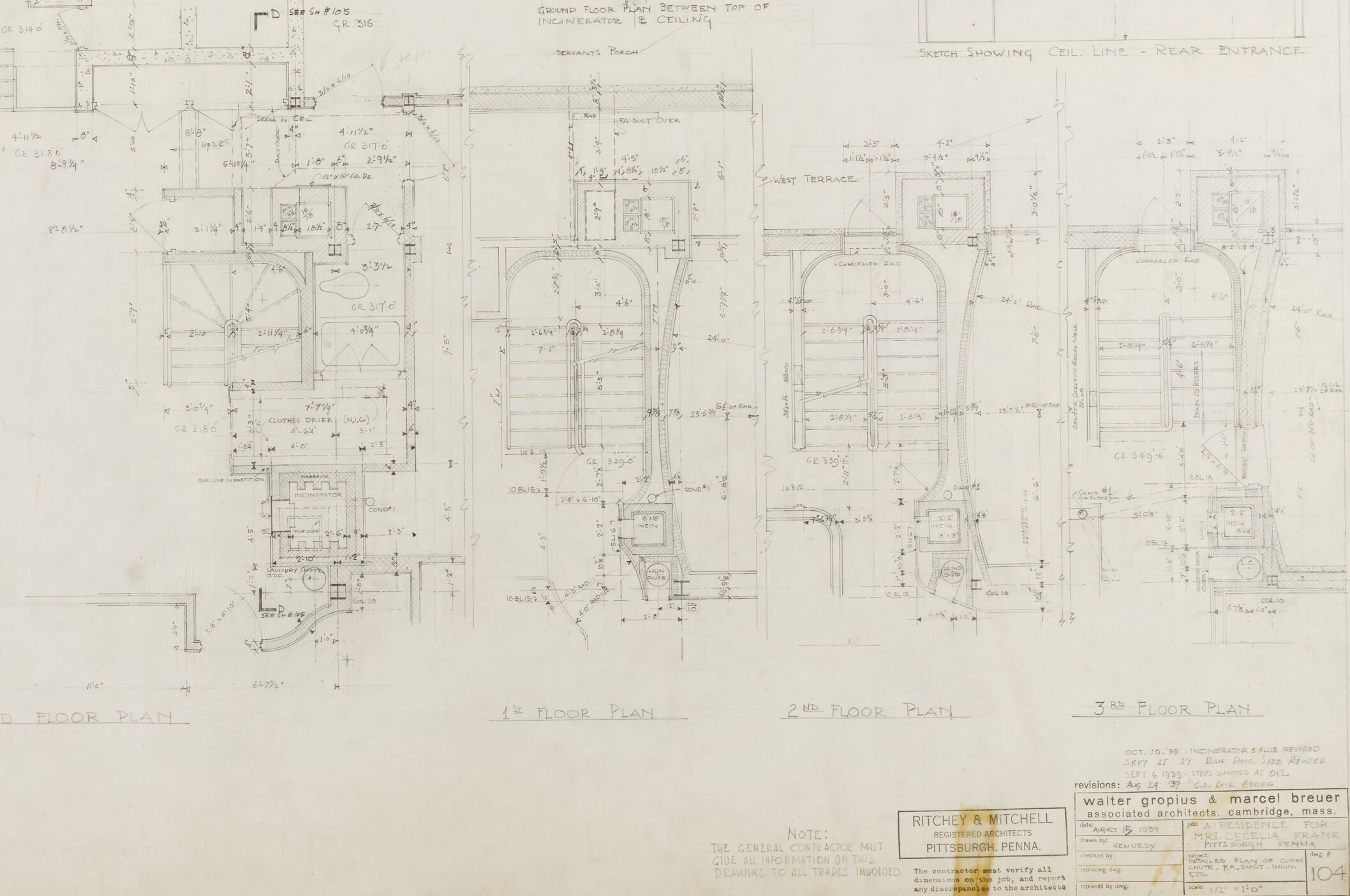
This image presents a set of architectural drawings for a multistory building. You can see multiple floor plans labeled as "Ground Floor Plan", "1st Floor Plan", "2nd Floor Plan", and "3rd Floor Plan". Each plan outlines the layout of rooms, hallways, doors, and other structural elements at their respective levels. The drawings are quite detailed and include annotations for measurements, construction materials, and references to other details. Architectural symbols indicate elements such as walls, door swings, windows, stairs, and furniture placements. The plans appear to be hand-drawn, which suggests they might be from a time when such plans were typically created manually before the widespread use of computer-aided design (CAD) software. On the right side of the sheet, there is a section labeled "Section Showing G.L. - Rear Entrance", which likely represents a cross-sectional view of the building at the indicated point. Such sections are useful for understanding vertical arrangements, such as floor heights and structural details. Additionally, there is a note section at the bottom right, which includes names and a reference to revisions, indicating that the drawing has been reviewed and possibly updated at the date specified. The names likely pertain to the architects or the firm responsible for the design. The drawing also includes a stamp or label marking from an architectural office in Pittsburgh, Pennsylvania. The paper itself shows signs of age and wear, with yellowing edges and some creasing, consistent with what one might expect from an older architectural document.
Created by gpt-4o-2024-05-13 on 2025-03-05
The image shows a detailed architectural blueprint. It includes various floor plans, specifically the ground floor plan, 1st-floor plan, 2nd-floor plan, and 3rd-floor plan. The drawings are meticulously detailed with precise measurements and annotations indicating dimensions, structural elements, and spatial layouts. In addition to the floor plans, there is a sketch towards the top right depicting the ceiling line of the rear entrance. The note section towards the bottom right provides information about the architectural firm responsible for the plans: Walter Gropius and Marcel Breuer, listed as associated architects based in Cambridge, Massachusetts. The document appears to be part of a larger set of architectural plans, possibly for a multi-story building based on the different floor plans shown. The blueprint paper shows signs of age and wear, with frayed edges and folds visible.
Anthropic Claude
Created by claude-3-haiku-20240307 on 2024-12-29
This image appears to be an architectural blueprint or floor plan. It shows detailed drawings and measurements for the different floors and sections of a building. The plans include a ground floor plan, a second floor plan, and a third floor plan, providing a comprehensive view of the building's structure and layout. The drawings contain various annotations and details, indicating this is a technical document used for construction or design purposes.
Created by claude-3-opus-20240229 on 2024-12-29
The image shows architectural plans and technical drawings for what appears to be multiple floor levels of a building. The plans depict the layout and dimensions of various rooms and spaces, with measurements and annotations provided. The bottom of the image contains a title block with additional details about the project, including the names "Ritchey & Mitchell Architects - Pittsbu" which likely refers to the architecture firm that created these plans. The drawings have a hand-drafted quality, suggesting they were produced before the widespread adoption of computer-aided design (CAD) software in architecture.
Created by claude-3-5-sonnet-20241022 on 2024-12-29
This is an architectural floor plan drawing showing multiple levels of a building. The drawing includes the ground floor plan, 1st floor plan, 2nd floor plan, and 3rd floor plan. Each level is detailed with precise measurements and dimensions. At the top of the drawing, there are also some smaller detail sections showing specific architectural elements like stairs and entrances. The plans appear to be technical drawings for what seems to be a commercial or institutional building, with various rooms, corridors, and structural elements clearly marked. The drawing is done in a professional architectural style with thin lines and detailed annotations. There's a title block in the bottom right corner indicating this was created by Walter Gropius & Marcel Breuer, associated architects from Cambridge, Massachusetts, for what appears to be a project for Ritchey & Mitchell in Pittsburgh, Pennsylvania. The drawing shows various architectural features including: - Arched elements that repeat on multiple floors - Detailed room layouts - Structural components - Circulation paths - Building dimensions and measurements The overall document appears to be a vintage architectural drawing, likely from the mid-20th century based on the drawing style and presentation.
Meta Llama
Created by us.meta.llama3-2-11b-instruct-v1:0 on 2025-03-11
The image presents a detailed floor plan of a building, showcasing the layout of various rooms and spaces. The plan is drawn in pencil on a piece of paper, with measurements and notes written in pencil along the edges and in the corners. * **Floor Plan:** * The floor plan is divided into three sections: ground floor, first floor, and second floor. * Each section features a series of rooms and corridors, with measurements and notes indicating the size and purpose of each space. * The plan includes a key or legend that explains the symbols and abbreviations used throughout the drawing. * **Measurements and Notes:** * The plan includes a range of measurements, including dimensions, room sizes, and door and window locations. * Notes are also included, providing additional information about the building's design and construction. * Some of the notes appear to be handwritten, while others may have been added later by a different person or at a different time. * **Paper and Drawing Style:** * The paper appears to be aged and worn, with tears and creases visible along the edges. * The drawing style is traditional, with a focus on hand-drawn lines and measurements. * The use of pencil and paper suggests that the plan was created before the widespread use of digital tools and software. Overall, the image provides a detailed and informative view of the building's floor plan, offering insights into its design and construction. The inclusion of measurements and notes adds depth and context to the drawing, making it a valuable resource for architects, builders, and historians.
Created by us.meta.llama3-2-90b-instruct-v1:0 on 2025-03-11
The image presents a detailed architectural plan, likely for a building or structure, showcasing various rooms and spaces. The plan is divided into three sections, each representing a different floor level: Ground Floor Plan, 1st Floor Plan, and 2nd Floor Plan. The 3rd Floor Plan is partially visible in the top-right corner. **Key Features:** * **Floor Plans:** Each floor plan is meticulously drawn, featuring various rooms, corridors, and staircases. The plans include measurements and labels to provide a clear understanding of the layout. * **Room Labels:** Some rooms are labeled, such as "Grand Floor Party Bedroom" and "Ladies' Toilet," while others remain unlabeled. * **Staircases:** Multiple staircases are depicted, connecting the different floors. * **Corridors:** Corridors and hallways are shown, providing access to various rooms and areas. * **Measurements:** Measurements are included throughout the plan, allowing for precise calculations and construction. * **Labels and Annotations:** Additional labels and annotations are scattered throughout the plan, providing further information about the design and layout. **Overall Impression:** The image appears to be a historical architectural plan, possibly from the early 20th century, given the style and notation used. The level of detail and precision suggests that this plan was created for a significant building or structure, likely with a specific purpose or function. The inclusion of labels and annotations indicates that the plan was intended for use by architects, builders, or other professionals involved in the construction process.
Amazon Nova
Created by amazon.nova-pro-v1:0 on 2025-01-11
The image is a detailed architectural drawing of a building's floor plan. It shows a layout with multiple rooms and areas, each marked with dimensions and annotations. The drawing includes various elements such as walls, doors, windows, and other structural details. The plan is divided into different sections, each labeled with a floor number, indicating it is a multi-story building. The drawing also includes a legend or key to explain the symbols and notations used.
Created by amazon.nova-lite-v1:0 on 2025-01-11
The image shows a set of architectural floor plans for a building. The plans depict the layout of three floors, with the ground floor, second floor, and third floor plans shown in the image. The plans are detailed, showing the dimensions of the rooms, the location of doors and windows, and the placement of structural elements such as columns and beams. The plans also include notes and labels indicating the names of the architects and the date of the plans. The image appears to be a technical drawing, with precise measurements and annotations.
Text analysis
Amazon