Machine Generated Data
Tags
Color Analysis
Categories
Imagga
| text visuals | 99.8% | |
| paintings art | 0.1% | |
Captions
Microsoft
created on 2018-03-22
| a close up of text on a whiteboard | 79% | |
| a close up of a whiteboard | 77.6% | |
| close up of text on a whiteboard | 76.3% | |
OpenAI GPT
Created by gpt-4 on 2025-03-07
The image you've provided is an architectural drawing or blueprint. This technical document contains detailed diagrams and notes on a particular construction project. Here's a description of its main features: 1. Different Views: The drawing includes several elevations and cross sections of a structure, showcasing different angles such as the "NORTH-WEST ELEVATION" and "NORTHEAST ELEVATION". 2. Annotations and Labels: Each part of the depicted structure is meticulously labeled with dimensions, materials, and construction details. We see notes like "Concrete Floor", "Steel Beam", "Brick Wall", and "Gravel Fill." 3. Omitted Section: There's an area on the top-right part of the drawing labeled "OMITTED", suggesting a section that was either removed or not included in the plan as of the date noted nearby ("July 31, 1941"). 4. Ramp Details: A significant portion of the drawing is dedicated to the "CROSS SECTION AND ELEVATION OF RAMP", which may indicate that the structure features some kind of inclined pathway. 5. Date and Architectural Details: The bottom corner of the drawing provides information about the architects or firm responsible for the design, "RITCHEY & MITCHELL PITTSBURGH, PENNA." There's also a date and names associated with revisions of the plans, including a revision on "7/28/41" by "Messercola Frank". 6. Drawing Scale and References: While hard to see in this resolution, usually such drawings include a scale for reference and may contain a legend or key explaining symbols and drawing conventions used. This document serves as a formal record and guide for the construction of the depicted structure and includes all necessary information to ensure accuracy and adherence to design during the building process.
Created by gpt-4o-2024-05-13 on 2025-03-07
The image is a detailed architectural blueprint drawing that appears to focus on the design of a garage. The blueprint includes various views and sections of the structure: 1. **Northwest Elevation**: This shows the side view of the garage. Details such as concrete used in the construction, placement of doors, windows, and structural elements are specified. 2. **Northeast Elevation**: Another side view opposite to the northwest elevation with specific markers and measurements. 3. **Cross Section and Elevation of Ramp**: This portion provides detailed views of the ramp construction within or leading to the garage, including cross-sectional details. 4. **Plan View**: Shows a top-down view of the garage layout with dimensions and placements of structural elements. 5. **Details**: Smaller detailed drawings provide specific construction techniques and materials, such as reinforcement, sheathing, and concrete usage. 6. **Compass Rose**: Indicates the orientation of the blueprint with the north direction marked. The blueprint is signed off by the architectural firms Ritchie & Mitchell from Pittsburgh, Penna, and Wilner Grijins & Marcel Breuer Associates from Cambridge, Mass. It's also noted that the blueprint is for a "Garage" designated by the number 78, with specific instructions and amendment dates provided in a notes section. The detailed annotations and date stamps (e.g., Aug 26, 1959) suggest thorough planning and revisions have been made to the design.
Anthropic Claude
Created by claude-3-haiku-20240307 on 2024-12-30
This image appears to be an architectural blueprint or technical drawing. It contains detailed plans and elevations for some kind of structure or building. The drawing includes various measurements, notations, and technical specifications, indicating this is likely an engineering or construction-related document. There are no human faces or identities visible in this image.
Created by claude-3-5-sonnet-20241022 on 2024-12-30
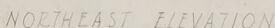
This is an architectural drawing showing various elevations and sections of what appears to be a garage structure. The drawing includes three main views: 1. Northwest Elevation 2. Cross Section and Elevation of Bank 3. Northeast Elevation The drawings are technical in nature, showing construction details, measurements, and annotations. They appear to be drawn by Ritchey & Mitchell from Pittsburgh, Pennsylvania. The drawings include structural elements like walls, foundations, and grade lines. The plans show both above-ground and below-grade details of the structure. The drawings are done in a professional architectural style, with clean lines and precise measurements. The paper appears aged, suggesting this is a historical document. There's a compass direction indicator in the corner of the drawing, and various technical notes and specifications are written throughout the document. This seems to be part of a larger set of construction documents, as indicated by the drawing number (43) in the bottom right corner.
Meta Llama
Created by us.meta.llama3-2-11b-instruct-v1:0 on 2025-03-17
The image presents a detailed blueprint for a structure, likely a building or bridge, with a focus on its elevation and cross-section. The blueprint is divided into sections, each providing specific information about the structure's design and construction. * **Title and Date** + The title of the blueprint is not visible. + The date of the blueprint is not visible. * **Elevation and Cross-Section** + The blueprint includes multiple elevations and cross-sections of the structure. + The elevations show the structure's exterior and interior features, including walls, windows, doors, and rooflines. + The cross-sections provide a detailed view of the structure's internal layout, including the location of beams, columns, and other structural elements. * **Dimensions and Measurements** + The blueprint includes various dimensions and measurements, such as lengths, widths, and heights. + These measurements are used to scale the structure and ensure accuracy during construction. * **Notations and Annotations** + The blueprint includes numerous notations and annotations, which provide additional information about the structure's design and construction. + These notations may include notes on materials, construction methods, and other relevant details. * **Scale and Grid** + The blueprint includes a scale and grid, which allows for precise measurements and calculations. + The scale is typically represented by a series of lines or symbols, while the grid provides a grid-like pattern for measuring distances and angles. * **Signatures and Labels** + The blueprint includes signatures and labels from various individuals involved in the design and construction process. + These signatures and labels may include the names of architects, engineers, contractors, and other stakeholders. In summary, the image presents a detailed blueprint for a structure, providing a comprehensive overview of its design and construction. The blueprint includes multiple elevations and cross-sections, as well as dimensions, measurements, notations, and annotations. The scale and grid are also included, allowing for precise measurements and calculations. Finally, the blueprint includes signatures and labels from various individuals involved in the design and construction process.
Created by us.meta.llama3-2-90b-instruct-v1:0 on 2025-03-17
The image depicts a technical drawing of a garage, likely created by an architect or engineer. The drawing is rendered in pencil on a large sheet of paper, with various sections and elevations labeled and detailed. **Key Features:** * **Northwest Elevation:** This section shows the front of the garage, including the door and any windows. * **Northeast Elevation:** This section depicts the side of the garage, highlighting any features such as vents or electrical outlets. * **Cross Section and Elevation of Ramp:** This section illustrates the slope and design of the ramp leading into the garage. * **Northwest Elevation:** This section provides a detailed view of the back of the garage, including any doors or windows. **Additional Details:** * The drawing includes notes and annotations throughout, providing additional information about the design and construction of the garage. * A small box in the bottom-right corner contains the names "Walter G. & Marcel Breuer" and "Ritchey & Mitchell," suggesting that these individuals or firms were involved in the design or construction of the garage. * The overall style of the drawing suggests that it was created in the mid-20th century, possibly during the 1950s or 1960s. **Conclusion:** This technical drawing provides a detailed and informative look at the design and construction of a garage. The various sections and elevations offer a comprehensive understanding of the garage's layout and features, while the notes and annotations provide additional context and insight.
Amazon Nova
Created by amazon.nova-lite-v1:0 on 2025-02-25
This image is a black-and-white architectural drawing. It is a technical blueprint of a building's design, showcasing various sections and elevations. The drawing includes labeled sections such as "Northwest Elevation," "Cross Section and Elevation of Ramp," and "Northwest Elevation." These sections provide detailed views of the building's exterior and interior features. The drawing also includes dimensions, measurements, and annotations to guide construction. The overall layout suggests a residential or commercial building with a mix of structural elements.
Created by amazon.nova-pro-v1:0 on 2025-02-25
The image shows a piece of paper with architectural drawings and text. The paper is folded in half, with the drawings on the left side and the text on the right side. The drawings appear to be a floor plan and elevation of a building, with dimensions and measurements indicated. The text on the right side includes the names of the architects, Walter Gropius and Marcel Breuer, and the name of the building, "Residence." The paper also has a watermark with the name "Ritchey & Mitchell" and the location "Pittsburgh, Penna." The image is in black and white, with a slightly faded appearance.
Text analysis
Amazon