Machine Generated Data
Tags
Color Analysis
Feature analysis
Amazon
| Document | 55.4% | |
Categories
Imagga
| text visuals | 99.9% | |
| paintings art | 0.1% | |
Captions
Microsoft
created on 2018-03-22
| a close up of text on a whiteboard | 75.9% | |
| a close up of a whiteboard | 73.7% | |
| close up of text on a whiteboard | 73% | |
OpenAI GPT
Created by gpt-4 on 2025-03-06
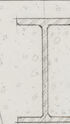
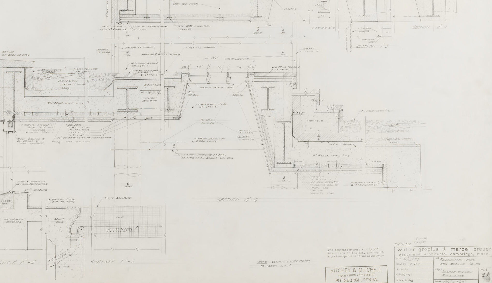
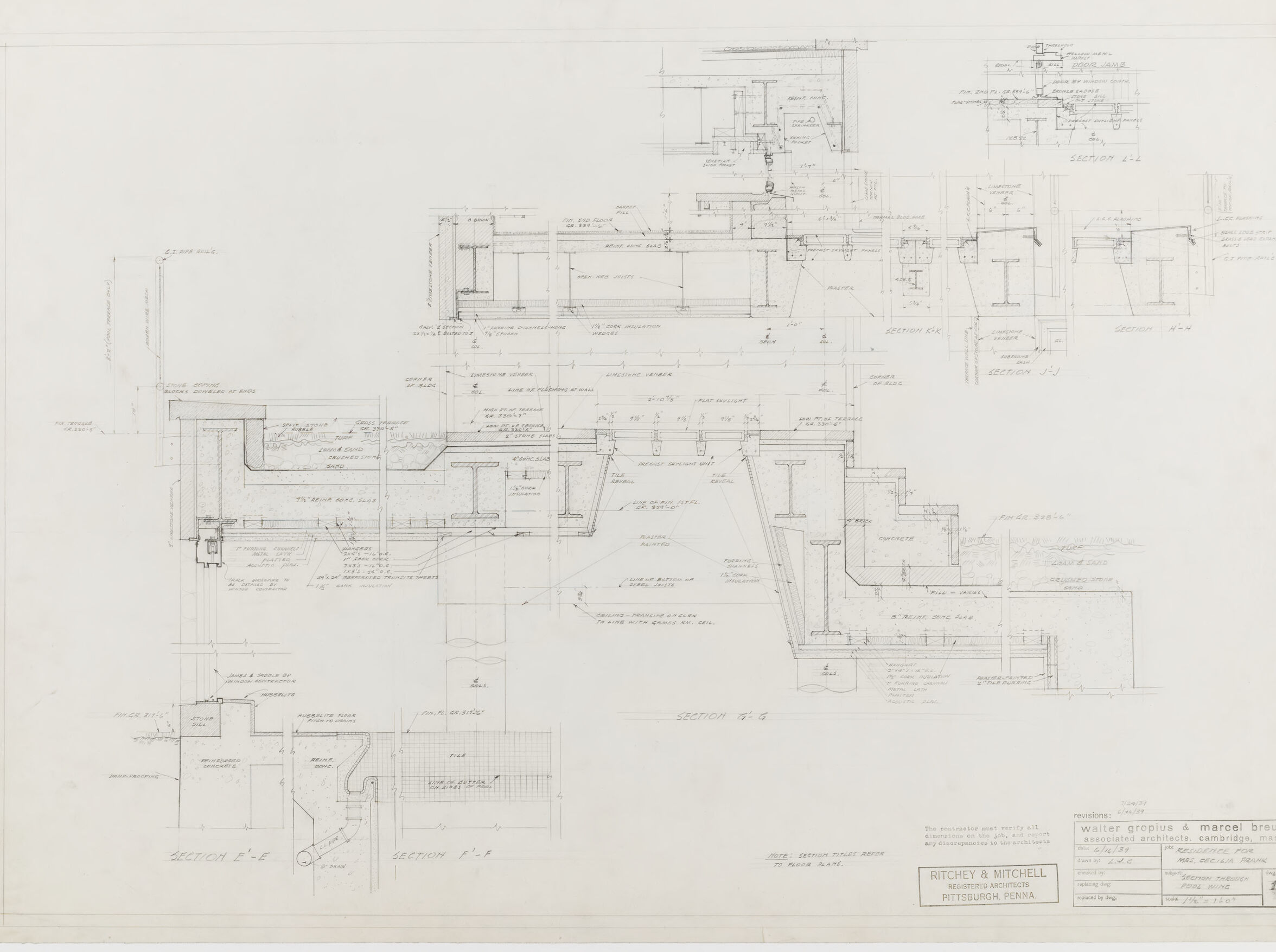
The image displays a detailed architectural drawing or blueprint. The drawing features a series of sections and details for a building, demonstrating the structure's intricacies, from supports and material layers to spatial dimensions and connections. On the drawing, there are multiple views shown. These could include cross-sectional views, elevations, and detailed construction notes, which give specific instructions or provide information about the materials and methods to be used during construction. The precise lines and annotations are characteristic of technical drawings used by architects and engineers. In the lower-right corner, there are names of individuals and/or firms, likely responsible for the creation of the blueprint. It indicates collaboration between a firm named "Ritchie & Mitchell" from Pittsburgh, Pennsylvania, and another firm or group, possibly indicated by designers or architects. There are also various annotations and stamps that might include the project name, scale, and drawing number, typical of architectural plans. This is a carefully crafted document intended to communicate the exact specifications of a building's design to those who will be involved in its construction.
Created by gpt-4o-2024-05-13 on 2025-03-06
The image is an architectural drawing with various cross-sections and detailed views of building elements. The drawing includes intricate notations and measurements that indicate the dimensions and construction methods for specific parts of the structure. The sections appear to be labeled with numbers and letters such as "SECTION F-F", "SECTION E-E", and "SECTION C-C," among others. These sections are detailed with components that include floors, walls, and structural supports. The notations include architectural terminologies and symbols, likely related to materials and construction processes. In the lower right corner, there is a title block that provides information about the project and the architects involved. The title block mentions: - Architectural firm: Ritchey & Mitchell, Pittsburgh, Penna. - Associated Architects: Walter Gropius & Marcel Breuer, Cambridge, Mass. - Drawing title: Sections through Floor and Roof - Scale: 3/4" = 1' 0" (or 1:16) - Date: 3/12/46 (March 12, 1946) - Project number: 51-12 - Drawing number: 14 From this, we can understand that the drawing is quite technical and is likely used for construction or detailed architectural analysis.
Anthropic Claude
Created by claude-3-haiku-20240307 on 2024-12-30
The image appears to be an architectural or engineering drawing or blueprint. It contains various technical diagrams, plans, and schematics with detailed measurements, annotations, and engineering specifications. The drawing seems to be related to an industrial or commercial structure, but without any identifying information, I cannot provide more specifics about the nature of the building or its purpose.
Created by claude-3-5-sonnet-20241022 on 2024-12-30
This is an architectural drawing showing detailed cross-sections of what appears to be a building design. The drawing is technically detailed with multiple sectional views labeled as "SECTION F-F," "SECTION G-G," and others. The plans show structural elements, dimensions, and various architectural details including beam placements, floor levels, and construction specifications. The drawing appears to be from an architectural firm, with credits shown at the bottom indicating "Walter Gropius & Marcel Breuer" as associated architects from Cambridge, Mass., and "Ritchey & Mitchell" from Pittsburgh, Pennsylvania. The drawing is done in a professional architectural style with precise lines and measurements, typical of mid-20th century architectural documentation.
Meta Llama
Created by us.meta.llama3-2-11b-instruct-v1:0 on 2025-03-13
The image presents a detailed architectural plan, likely for a building or structure, created by Walter Gropius and Marcel Breuer. The plan is drawn in pencil on a large sheet of paper, with various sections and details labeled. * **Title and Credits** * The title of the plan is not visible, but it appears to be a collaborative effort between Walter Gropius and Marcel Breuer. * The names of the architects are written in small text at the bottom right corner of the plan. * **Plan Layout** * The plan is divided into several sections, each with its own set of details and labels. * The sections appear to be labeled with letters or numbers, indicating different areas of the building or structure. * **Details and Labels** * Various details are labeled throughout the plan, including doorways, windows, staircases, and other architectural features. * The labels are written in a clear and legible font, making it easy to understand the purpose and function of each feature. * **Scale and Measurements** * The plan includes a scale and measurements, allowing the viewer to understand the size and proportions of the building or structure. * The scale is likely in feet or meters, and the measurements are provided in inches or centimeters. * **Additional Information** * The plan includes additional information, such as notes and annotations, that provide context and clarify specific details. * The notes are written in a smaller font and are scattered throughout the plan, providing further insight into the design and construction of the building or structure. Overall, the image presents a detailed and well-organized architectural plan that provides a comprehensive understanding of the building or structure's design and layout. The plan is likely used for construction or renovation purposes, and its level of detail suggests that it was created by experienced architects.
Created by us.meta.llama3-2-90b-instruct-v1:0 on 2025-03-13
The image presents a detailed architectural blueprint, showcasing the intricate design and layout of a building. The blueprint is rendered in black ink on a white background, with various sections and components labeled for clarity. **Key Features:** * **Sectional Views:** The blueprint includes multiple sectional views, providing a comprehensive understanding of the building's structure and layout. * **Labeling:** Each section and component is meticulously labeled, ensuring that the design is easily interpretable. * **Scale:** A scale is provided in the bottom-right corner, allowing for accurate measurements and scaling of the design. * **Architectural Firm:** The blueprint is attributed to Ritchey & Mitchell, a renowned architectural firm, as indicated by the logo in the bottom-right corner. * **Date:** Although the date of creation is not explicitly stated, the style and presentation suggest that it may be from an earlier era, possibly the mid-20th century. **Overall Impression:** The image exudes a sense of professionalism and attention to detail, reflecting the expertise of the architectural firm responsible for its creation. The use of a traditional medium, such as ink on paper, adds a touch of nostalgia and authenticity to the design. Overall, the image provides a fascinating glimpse into the world of architecture and design, showcasing the meticulous planning and execution that goes into creating a functional and aesthetically pleasing building.
Amazon Nova
Created by amazon.nova-lite-v1:0 on 2025-01-13
The image is a technical architectural drawing, likely from a construction or engineering project. The drawing is composed of multiple sections, each showing different parts of the structure, including floor plans, elevations, and cross-sections. The drawing includes detailed annotations, measurements, and labels indicating various components and materials. The title of the drawing is "Ritchey & Mitchell, Registered Architects, Pittsburgh, Pennsylvania," indicating the firm responsible for the design. The drawing appears to be a professional, detailed blueprint used for construction purposes.
Created by amazon.nova-pro-v1:0 on 2025-01-13
The image is a blueprint of a building. The blueprint is a technical drawing that includes measurements, dimensions, and other details necessary for construction. The blueprint is divided into several sections, each showing a different aspect of the building's design. The top section shows the floor plan, while the bottom section shows the elevation and section views. The blueprint also includes notes and annotations that provide additional information about the building's design.
Text analysis
Amazon