Machine Generated Data
Tags
Color Analysis
Feature analysis
Amazon
Clarifai

Clarifai
| Whiteboard | 62.4% | |
Categories
Imagga
created on 2018-03-22
| text visuals | 100% | |
Captions
Microsoft
created by unknown on 2018-03-22
| a close up of text on a whiteboard | 76.9% | |
| a close up of a whiteboard | 74.4% | |
| close up of text on a whiteboard | 74.2% | |
Clarifai
No captions written
Salesforce
Created by general-english-image-caption-blip on 2025-05-06
a photograph of a drawing of a plan for a kitchen
Created by general-english-image-caption-blip-2 on 2025-06-28
a drawing of a building with plans and drawings
OpenAI GPT
Created by gpt-4 on 2025-03-07
The image shows an architectural drawing or blueprint, which includes plans and sections of a building or structure. The drawing displays technical details such as measurements, construction materials, design specifications, and component details. It is a very detailed plan, with various notes and labels that indicate the dimensions and materials intended for different parts of the construction. There are several views and cross-sections providing different perspectives, such as floor plans and elevations of doorways or other elements, ensuring a comprehensive understanding of the architect's design. The style of the lines and text indicates that this is a hand-drafted document, typical of architectural plans before the widespread use of computer-aided design (CAD). The bottom right corner often contains information about the project, architects, and sometimes the date and location.
Created by gpt-4o-2024-05-13 on 2025-03-07
This image depicts a detailed architectural blueprint with various technical drawings and specifications. The blueprint includes multiple sectional views and plans for specific components of a building's structure, focusing on sliding doors and the associated architectural elements.
Key elements include:
- Vertical and Horizontal Sections: Detailed technical drawings of both vertical and horizontal sections highlight measurements and construction details, showing the relationship between different components like plaster, doorframes, and finishing channels.
- Door Mechanisms and Frames: The bottom left and center drawings specifically demonstrate the structural details and mechanisms for sliding doors, including measurements, material specifications, and assembly instructions.
- Labeling and Annotations: The blueprint is annotated with measurements, material notes, and instructions for the construction and installation process. Specific terms such as "plaster," "finish channel," and "wood plate" are used to denote materials and parts.
- Architectural Details: The drawing includes detailed viewpoints of complex architectural elements such as interlocking door tracks and jamb sections, essential for ensuring precise construction and proper installation.
- Architect Information: The blueprint is credited to the firms "Ritchey & Mitchell Registered Architects, Pittsburgh, Penna" and "Walter Gropius & Marcel Breuer, Associated Architects, Cambridge, Mass." This credits the architects responsible for the design.
As typical for architectural drawings, the diagram uses fine lines, precise measurements, and scaled drawings to communicate the intricate details required for construction and understanding the assembly of the structural components.
Anthropic Claude
Created by us.anthropic.claude-3-5-sonnet-20241022-v2:0 on 2025-06-24
This image appears to be an architectural drawing or blueprint, specifically a detailed floor plan or construction document. It's drawn in a technical style with various sections, elevations, and details shown. The drawing is created by Ritchey & Mitchell, Registered Architects from Pittsburgh, Pennsylvania, as indicated in the title block at the bottom of the sheet. The drawing shows various architectural elements including walls, doors, and other building components with precise measurements and annotations. The drawing appears to be done in pencil or ink on paper and has that classic, vintage architectural drawing appearance typical of hand-drafted construction documents from before the era of computer-aided design (CAD).
Created by claude-3-haiku-20240307 on 2024-12-30
The image appears to be a detailed engineering diagram or technical drawing. It contains various technical specifications, measurements, and diagrams of what seems to be some kind of mechanical or industrial device. The drawing appears to be very precise and technical in nature, with various annotations, labels, and measurements throughout. There are no human faces or identifiable individuals present in this image.
Created by claude-3-opus-20240229 on 2024-12-30
The image shows architectural drawings and plans for what appears to be a building called "Ritchey & Mitchell Residence, Pittsburgh, Penna." The plans include various elevations, sections, and detailed drawings of architectural elements like doors, windows, and wall treatments. The drawings are labeled with dimensions and construction notes. In the bottom right corner, there is a title block with the architects' names (Walter Ritchey & Scott T. Mitchell) and the project location (Pittsburgh, PA).
Created by claude-3-5-sonnet-20241022 on 2024-12-30
This image appears to be an architectural drawing or technical blueprint showing various detailed sections and elevations. The drawing includes multiple views and cross-sections of what seems to be interior architectural elements or built-in furniture pieces. The plans are quite detailed, showing precise measurements and construction specifications. At the bottom of the drawing, there's information indicating it was created by Ritchey & Mitchell, architects from Pittsburgh, Pennsylvania. The drawing style is typical of mid-century architectural documentation, with clean lines and careful dimensioning. There appear to be both plan views and sectional details that would help guide construction or installation of the designed elements.
Meta Llama
Created by us.meta.llama3-2-11b-instruct-v1:0 on 2025-03-17
The image presents a detailed architectural drawing of a building's floor plan, showcasing various rooms and spaces. The drawing is rendered in black ink on white paper, with precise lines and measurements indicating the layout of the building.
Key Features:
- Floor Plan: The drawing depicts the ground floor of the building, featuring several rooms, including a kitchen, dining area, living room, bedrooms, and bathrooms.
- Room Dimensions: Each room is labeled with its dimensions, providing a clear understanding of the space's size and layout.
- Door and Window Locations: The drawing indicates the location of doors and windows, allowing for easy navigation and understanding of the building's layout.
- Architectural Details: The drawing includes various architectural details, such as archways, columns, and fireplaces, which add character to the building's design.
- Scale: The drawing is scaled to 1/4 inch = 1 foot, ensuring accuracy and precision in the representation of the building's layout.
- Creator: The drawing is attributed to Walter Groelius and Marcel Breuer, two renowned architects who worked together on this project.
Overall Impression:
The drawing provides a comprehensive and detailed representation of the building's floor plan, showcasing the architects' attention to detail and commitment to creating a functional and aesthetically pleasing space. The use of precise measurements and architectural details adds depth and complexity to the drawing, making it a valuable resource for architects, builders, and anyone interested in the building's design and layout.
Created by us.meta.llama3-2-90b-instruct-v1:0 on 2025-03-17
The image presents a detailed architectural blueprint, showcasing the floor plan of a building. The blueprint is divided into several sections, each representing a different area of the structure. The left side of the blueprint features a large section with various rooms and corridors, while the right side displays smaller sections that appear to be individual rooms or offices.
In the bottom-right corner of the blueprint, a small box contains text that reads "RITCHEY & MITCHELL" and "PITTSBURGH, PENNA." This suggests that the blueprint was created by the architectural firm Ritchey & Mitchell, which was based in Pittsburgh, Pennsylvania.
Overall, the image provides a comprehensive view of the building's layout and design, offering valuable insights into its architecture and functionality.
Amazon Nova
Created by amazon.nova-lite-v1:0 on 2025-02-25
The image is a technical architectural drawing of a building. The drawing includes various sections and details, such as floor plans, elevations, and structural details. The drawing is labeled with the names of the architects, "Walter Gropius & Marcel Breuer," and the location, "Cambridge, Mass." The drawing also includes a date, "1965," and the name of the firm, "Ritchey & Mitchell." The drawing is on a white background and appears to be a blueprint or technical drawing used for construction purposes.
Created by amazon.nova-pro-v1:0 on 2025-02-25
The image shows a technical drawing of a building. The drawing consists of several sections, including a floor plan, elevation, and details of specific elements. The floor plan shows the layout of the building, including rooms and corridors. The elevation shows the building's exterior, including windows and doors. The details section provides information on specific elements, such as sliding doors and jamb sections. The drawing is labeled with various dimensions and annotations, indicating the building's size and features.
Google Gemini
Created by gemini-2.0-flash on 2025-05-07
Here's a description of the image based on the details provided:
Overall Impression:
The image presents an architectural technical drawing, specifically detailing the construction and design of sliding doors. It appears to be a blueprint or schematic created by architects, likely for construction purposes.
Key Elements:
- Detailed Drawings: There are multiple detailed drawings, including sections, plans, and elevations, showing different views and aspects of the sliding door assembly.
- Annotations and Dimensions: The drawings are heavily annotated with measurements, materials, and construction notes.
- Sliding Door Mechanism: The image emphasizes the inner workings of the sliding door mechanism, showcasing how the doors slide, their relationship to the floor, jambs, and overhead structure.
Text and Signatures:
- Architects' Names: The names "Walter Gropius & Marcel Breuer, associated architects, Cambridge, Mass." are prominently displayed.
- Firm Information: "Ritchey & Mitchell, Registered Architects, Pittsburgh, Penna." is mentioned, suggesting the project might be a collaboration between firms.
Purpose:
This image serves as a construction document for the implementation of the sliding door design. It provides essential information for builders and contractors to accurately construct the doors.
Created by gemini-2.0-flash-lite on 2025-05-07
Here's a description of the image:
This is a technical drawing, likely an architectural blueprint, showing detailed plans for "Full Size Detail Plans Sliding Doors". The drawing is composed of multiple views and sections, providing comprehensive information about the design and construction of sliding doors. The drawing style is characteristic of architectural blueprints, utilizing lines, annotations, and measurements to define the components, dimensions, and assembly of the doors. The title "RITCHEY & MITCHELL, REGISTERED ARCHITECTS PITTSBURGH, PENNA" is found at the bottom of the document, in addition to the name "walter gropius & marcel breuer", indicating it was drawn in association with the architects.
Mistral Pixtral
Created by us.mistral.pixtral-large-2502-v1:0 on 2025-05-31
The image is an architectural blueprint, which appears to be a detailed floor plan and sectional view of a building. Here is a detailed summary of the various components visible in the blueprint:
Floor Plan:
- The left side of the blueprint shows a floor plan with various rooms and spaces.
- The plan includes labels for different areas such as "Entrance Hall," "Living Room," "Dining Room," "Kitchen," and "Bedrooms."
- There are also indications of structural elements like walls, doors, and windows.
- Dimensions and measurements are provided for various parts of the floor plan.
Sectional Views:
- The right side of the blueprint contains sectional views of the building.
- These sections show the vertical layout of the building, including the arrangement of floors, walls, and roof structure.
- The sections provide detailed information about the height and thickness of walls, floor levels, and ceiling heights.
Elevations:
- There are elevation drawings that show the exterior views of the building from different sides.
- These elevations include details of windows, doors, and other architectural features.
Details and Annotations:
- The blueprint includes various annotations and notes that provide additional information about the design and construction.
- There are references to specific materials, finishes, and construction techniques.
- The blueprint also includes a legend or key that explains the symbols and abbreviations used in the drawing.
Architect Information:
- The bottom right corner of the blueprint includes the names of the architects and the firm responsible for the design.
- It mentions "Walter Gropius & Marcel Breuer" as the consulting architects and "Mitchell & Ritchey" as the associated architects.
- The location of the architectural firm is noted as Pittsburgh, Pennsylvania.
Scale and Date:
- The blueprint includes a scale bar, which helps in understanding the actual dimensions of the building.
- The date of the drawing is also mentioned, which is April 1940.
Overall, the blueprint provides a comprehensive overview of the architectural design of a building, including its layout, structural details, and exterior appearance.
Qwen
Created by Qwen/Qwen2.5-VL-7B-Instruct on 2025-07-20
This image is an architectural drawing, likely a set of detailed construction plans for a project. The drawing includes multiple views and sections, providing precise measurements and specifications for a door and sliding door system. Here's a breakdown of what is visible:
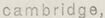
Title Block: Located in the bottom right corner, the title block contains the names and affiliations of the architects (Walter Gropius & Marcel Breuer), the date (February 4, 1940), and the project details (Residence for Mrs. Cecelia K. Frank, Pittsburgh, Penna.). It also includes a drawing number (215) and a note about revisions.
Detail Drawings: The drawing includes various sections and elevations, showing the construction details of the sliding door system.
- Jamb Section: A cross-sectional view of the door frame, including the dimensions of the door frame, hardware, and the separation of the doors.
- Elevation and Section Views: These provide a side and cross-sectional view of the door and sliding door system, showcasing how the doors align and the overall structure.
Materials and Components: The detailed drawings include references to materials and components such as "Flush Sliding Doors," "Sycamore Veneer," "Syc Plywood," "Floor Door Guide," "Nailing Block," "Door Guide," "Metal Strips," and "Hangers."
Dimensions and Notes: The drawing includes precise measurements with dimensions given in inches, such as door thickness, panel sizes, and clearances. Notes provide additional instructions and specifications, such as the installation of door guides and the locations for nailing blocks.
Architects and Drawings: The drawing credits "Ritchey & Mitchell, Registered Architects, Pittsburgh, Penna."
The overall purpose of this drawing is to provide a comprehensive set of guidelines for the construction of sliding doors, ensuring that the components fit together correctly and meet the design specifications set by the architects.
Created by Qwen/Qwen2.5-VL-72B-Instruct on 2025-07-20
This image is an architectural drawing or blueprint, specifically a detailed design for a closet system. It includes various sections, elevations, and plan views, providing comprehensive construction instructions. Here are some key elements of the drawing:
Sections and Details:
- Full Size Detail Through Sliding Doors: This section shows the detailed construction of the sliding door system, including the door tracks, door guides, and the materials used.
- Jamb Section Through Sliding Doors: This section provides a vertical cross-section through the jamb area of the sliding doors, showing the door frame, door stops, and the door guide mechanism.
Materials and Components:
- The drawing specifies the materials used, such as Sycamore veneer for the sliding doors, plywood for various components, and chrome-plated handles.
- Details about the door guides, flooring, and wall construction are also included.
Dimensions and Notes:
- Precise dimensions are provided for various parts of the closet system, ensuring accurate construction.
- Notes and instructions are included to clarify specific details, such as the need for angle irons or the dimensions of certain components.
Architectural Information:
- The drawing is attributed to Walter Gropius & Marcel Breuer, associated architects based in Cambridge, Massachusetts.
- The project is for the residence of Mrs. Cecelia K. Frank in Pittsburgh, Pennsylvania.
- The drawing number is 215, and it was drawn by Landsberg on February 4, 1940.
Additional Views:
- Elevation View: Shows the front view of the closet, including the sliding door system and the overall height.
- Plan View: Provides a top-down view of the closet, showing the layout and the position of the sliding doors when open.
This blueprint is a technical document that architects and builders use to construct the specified closet system accurately and efficiently.
Text analysis
Amazon