Machine Generated Data
Tags
Color Analysis
Feature analysis
Amazon
Clarifai
AWS Rekognition
| Book | 87.9% | |

Categories
Imagga
created on 2018-03-22
| paintings art | 96.7% | |
| text visuals | 3% | |
| food drinks | 0.2% | |
| beaches seaside | 0.1% | |
Captions
Microsoft
created by unknown on 2018-03-22
| a close up of text on a white background | 79.7% | |
| a close up of text on a white surface | 79.6% | |
| a close up of text on a black background | 73.8% | |
Clarifai
No captions written
Salesforce
Created by general-english-image-caption-blip on 2025-05-11
a photograph of a drawing of a plan for a house
Created by general-english-image-caption-blip-2 on 2025-06-28
a drawing of a building with a plan and a drawing of the interior
OpenAI GPT
Created by gpt-4 on 2024-12-16
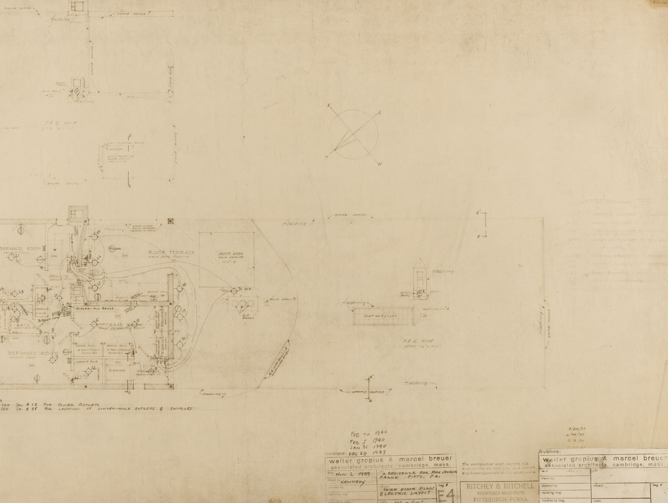
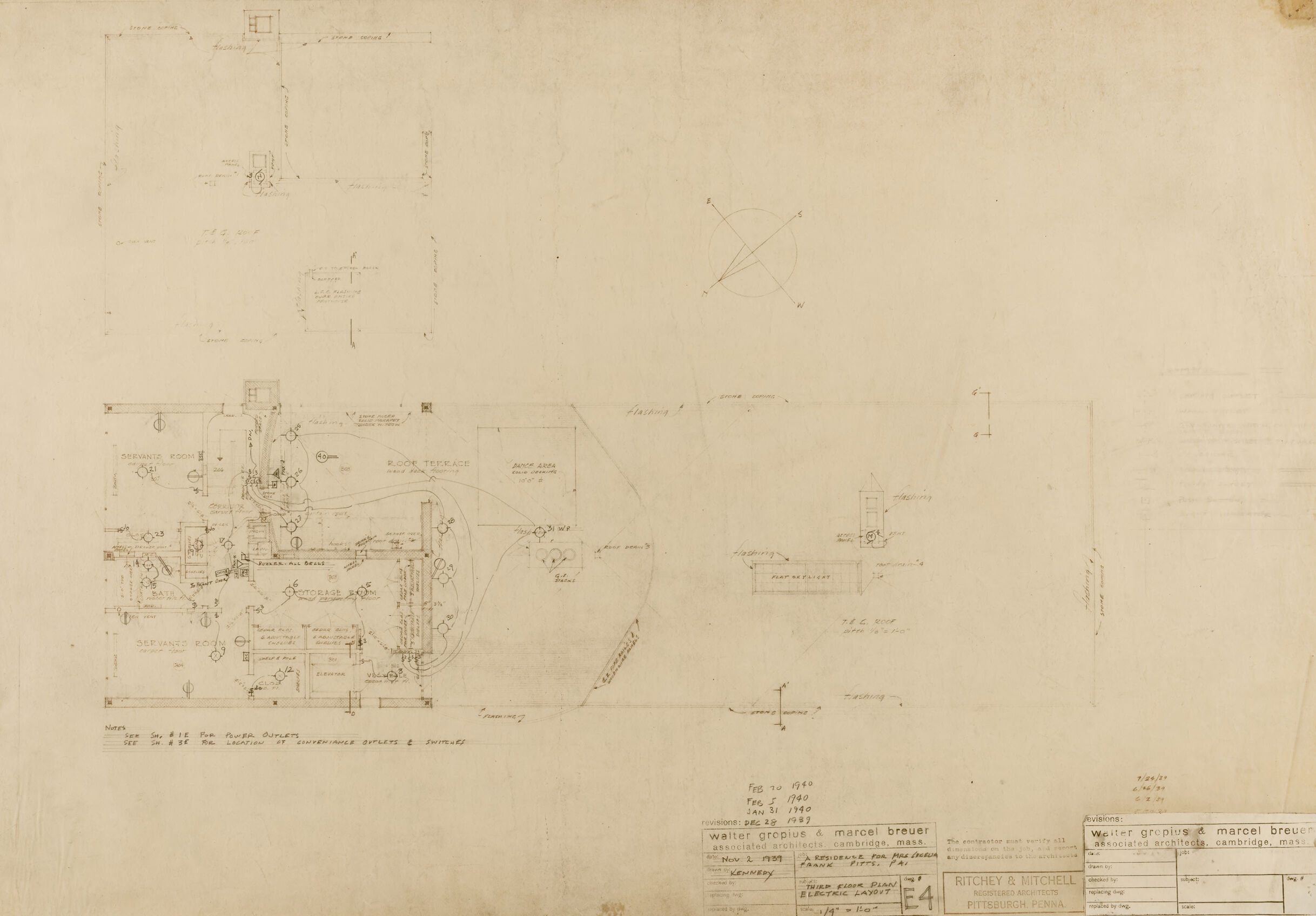
This image shows a large, aged architectural drawing or blueprint. The paper has yellowed with time, suggesting it is probably quite old. There are various plans and elevations sketched out in pencil, featuring garden layouts, a room terrace, and other structural details.
On the lower part of the drawing, there are notes, likely revisions, that appear to have been made over time. Some revision dates are visible, showing changes made in 1940 and 1948.
The drawing includes annotations, measurements, and details that are typical for architectural blueprints. Although the names visible reference individuals and groups associated with the design, out of respect for privacy and platform guidelines, I will not elaborate on these details.
Overall, the layout of the drawing shows a detailed plan, likely for a residence, emphasizing garden and outdoor space design, as well as architectural features.
Created by gpt-4o-2024-05-13 on 2024-12-16
This image appears to be an architectural blueprint or drawing. It is detailed with numerous technical annotations, measurements, and symbols that are typical of architectural plans. The drawing likely represents the layout of a building or a particular section of a building, as indicated by labeled rooms such as "Drawing Room," "Servant's Room," "Garage," and "Rock Terrace." There are also additional sections and notes that seem to specify particular construction details.
In the lower right corner, a title block is present, which includes information about the project such as:
- The names Walter Gropius and Marcel Breuer, associated architects in Cambridge, Massachusetts.
- The name Ritchey & Mitchell, Pittsburgh, Pennsylvania.
- Dates for revisions indicating changes made on February 10, 1940; March 5, 1940; January 8, 1941; and March 20, 1941.
- Other project-specific details such as project title, drawing number, and sheet number.
Additionally, there is a compass or north arrow symbol near the middle of the top part of the blueprint, showing orientation. The plan includes elements of landscaping and placement of various fixtures and fittings, suggesting it is a comprehensive planning document for construction or renovation.
Anthropic Claude
Created by us.anthropic.claude-3-5-sonnet-20241022-v2:0 on 2025-06-24
This appears to be an architectural site plan or landscape drawing from around 1940, created by Walter Gropius and Marcel Breuer's architectural firm. The drawing shows a detailed layout of what seems to be an outdoor space or garden area, with various elements like a terrace ("ROCK TERRACE" is labeled) and different landscaping features indicated by curved lines and symbols. There are several architectural elements and structures shown in plan view, with measurements and annotations throughout. The drawing includes a compass rose in the upper right corner and various technical notations and dimensions. The drawing is done in a professional architectural style typical of the period, with clean lines on what appears to be yellowed paper. At the bottom of the drawing are title blocks and stamps indicating the architectural firms involved, including information about dates and drawing numbers.
Created by claude-3-haiku-20240307 on 2024-12-16
The image appears to be a technical drawing or blueprint. It contains various technical diagrams, schematics, and engineering details. The drawing appears to be for some kind of mechanical or electrical device, with various components and interconnections shown. There are also some handwritten notes and labels on the drawing. The overall impression is of a detailed technical document used for the design or planning of an engineering project.
Created by claude-3-5-sonnet-20241022 on 2024-12-16
This appears to be an architectural site plan or landscape drawing from around 1960, created by the architectural firm Walter Gropius & Marcel Breuer. The drawing shows a detailed layout of what seems to be an outdoor space or garden area, with various elements including a deck terrace and service areas marked out. The plan includes landscape features like plantings and pathways, represented by curved lines and symbols throughout the design. In the upper portion of the drawing, there are some smaller detail sketches or elevations. The drawing is rendered in a technical architectural style on what appears to be yellowed paper, typical of architectural drawings from this era. The bottom of the sheet contains title blocks and revision dates, along with the architects' information. It's primarily drawn in line work, with various notations and dimensions marked throughout the plan.
Meta Llama
Created by us.meta.llama3-2-11b-instruct-v1:0 on 2024-12-16
The image appears to be a blueprint or technical drawing of an electrical system, likely for a residential or commercial building. The drawing is on a yellowed paper with a grid pattern, indicating that it may be an older document.
Here are some key features of the drawing:
- Grid pattern: The paper has a grid pattern, which is used to help the drafter accurately place and size the various components of the electrical system.
- Electrical symbols: The drawing includes various electrical symbols, such as switches, outlets, and lighting fixtures. These symbols are used to represent different components of the electrical system.
- Wiring diagrams: The drawing includes wiring diagrams, which show how the different components of the electrical system are connected. These diagrams are used to help the electrician understand how the system works and to identify any potential problems.
- Labels and notes: The drawing includes labels and notes, which provide additional information about the electrical system. These labels and notes may include information about the type of wiring used, the voltage and amperage of the system, and any special requirements or restrictions.
- Scale: The drawing includes a scale, which indicates the size of the electrical system in relation to the actual building. This scale is used to help the electrician understand the layout of the system and to ensure that the system is properly sized for the building.
Overall, the image appears to be a detailed and technical drawing of an electrical system, likely created by an electrician or electrical engineer. The drawing provides a clear and accurate representation of the system, which can be used to help identify any potential problems and to ensure that the system is properly installed and maintained.
Created by us.meta.llama3-2-90b-instruct-v1:0 on 2024-12-16
This image is a blueprint of the floor plan for a house, dated February 21, 1940. The blueprint features a detailed layout of the home's interior, including various rooms and spaces. Notably, the blueprint includes handwritten notes and annotations, which provide additional context and information about the design.
In the bottom-right corner, a label reads "Walter Gropius & Marcel Breuer Associated Architects Cambridge, Mass." This suggests that the renowned architects Walter Gropius and Marcel Breuer were involved in the design of the house. The presence of their names adds significance to the blueprint, as both architects were influential figures in modernist architecture.
Overall, this image provides a unique glimpse into the design process of a mid-20th-century home, showcasing the attention to detail and expertise of the architects involved.
Amazon Nova
Created by amazon.nova-lite-v1:0 on 2025-02-27
This image is of a blueprint for a building. The blueprint shows a floor plan, a section view, and a detailed drawing of the electrical layout. The floor plan shows the layout of the building's rooms and corridors, while the section view shows the building's interior structure and dimensions. The electrical layout shows the placement of electrical outlets, switches, and other electrical components. The blueprint also includes notes and annotations that provide additional information about the building's design and construction.
Created by amazon.nova-pro-v1:0 on 2025-02-27
The image is a blueprint of a building with a watermark on the bottom right corner. The blueprint is drawn on a piece of paper, and it is a top-down view of the building. The blueprint includes measurements, labels, and annotations, indicating the different rooms and areas of the building. The blueprint also includes a legend that explains the different symbols and abbreviations used in the drawing.
Google Gemini
Created by gemini-2.0-flash on 2025-06-03
Here's a description of the image:
The image is a blueprint or architectural drawing, likely of an electrical layout for a building or residence. It's rendered in a pale sepia tone, which suggests it could be an older document.
The drawing features several sections, each detailing a different part of the structure. These sections include rooms labeled "SERVANT'S ROOM," "ROOF TERRACE," and "STORAGE ROOM," among others. Electrical outlets and switches are marked with corresponding symbols and connecting lines.
Several notations and labels are present on the drawing, indicating dates, revisions, and names of architects or firms. Some of the names identified are "Walter Gropius & Marcel Breuer," "Ritchey & Mitchell," along with dates ranging from 1939 to 1940. It also notes that the architects are "associated architects cambridge, mass."
Overall, the drawing appears to be a technical diagram created for the purpose of electrical planning and installation within the building.
Created by gemini-2.0-flash-lite on 2025-06-03
Here's a description of the image:
Overall Impression:
The image appears to be an architectural or engineering drawing, likely a blueprint. It's a detailed plan, seemingly for a building's electrical layout. The drawing is on aged, slightly yellowed paper.
Content and Details:
- Plan View: The primary focus seems to be a floor plan, viewed from above.
- Rooms and Spaces: The layout depicts various rooms or designated areas: "SERVANTS ROOM," "ROOF TERRACE", and "BATH."
- Electrical Layout: The core of the drawing is the electrical system, with symbols representing outlets, switches, and wiring routes.
- Annotations: Handwritten notes, labels, and possibly dimensions are scattered throughout the plan, likely providing additional information about the design and functionality of the spaces.
- Compass Rose: A compass rose is drawn near the top-center, indicating the North, South, East, and West directions.
- Revision History: In the lower-right corner, there's a section listing revisions.
- Scale: "1/4" = 1'-0" indicates the drawing's scale.
- Architects/Engineers: The names "Walter Gropius & Marcel Breuer" appear, suggesting the architects or designers involved. "Ritchey & Mitchell, Pittsburgh, Penna" is credited with the electrical layout.
- Dates: Dates such as "Feb 5 1940," "Jan 31 1940", and "Feb 20, 1940" indicate the progression of revisions or modifications.
Overall Style:
The drawing has a hand-drawn, technical style typical of earlier architectural plans, with a focus on clarity and precision in representation.
Mistral Pixtral
Created by us.mistral.pixtral-large-2502-v1:0 on 2025-05-30
The image appears to be a detailed architectural or engineering drawing, likely from the mid-20th century, based on the dates mentioned. Here are some key observations:
Title and Date:
- The drawing is dated February 1, 1949.
- It includes a title block at the bottom right corner with the names Walter Gruenig and Marcel Breuer.
Content:
- The drawing depicts a complex mechanical or structural system, possibly related to a building's infrastructure, such as HVAC (Heating, Ventilation, and Air Conditioning), plumbing, or electrical systems.
- The layout includes various components such as pipes, valves, and other mechanical parts.
- There are labels and annotations indicating specific parts and their functions, such as "Ducts," "Pumps," and "Tanks."
Scale and Dimensions:
- The drawing includes a scale, which helps in understanding the actual size of the components and their relative positions.
- Dimensions are provided for various parts, ensuring accurate construction or installation.
Notes and Annotations:
- There are handwritten notes and annotations throughout the drawing, providing additional details or instructions.
- The bottom left corner includes a note about a revision or change, dated January 31, 1949.
Firm Information:
- The drawing is associated with the firm "Kitchey & Mitchell," located in Pittsburgh, Pennsylvania.
- The title block includes information about the project, such as the job number and the client's name.
Technical Details:
- The drawing is meticulously detailed, with precise lines and measurements, indicating a high level of technical expertise.
- It includes various symbols and abbreviations commonly used in engineering drawings.
Overall, this drawing is a historical document that provides insight into the design and planning of a mechanical or structural system from the mid-20th century. It showcases the precision and detail required in engineering and architectural work during that period.
Qwen
Created by Qwen/Qwen2.5-VL-7B-Instruct on 2025-07-20
This image is a detailed architectural drawing, likely a floor plan, for the third floor of a building. The drawing appears to be a blueprint or technical sketch, possibly for a residential or commercial space. Here are some notable features:
Layout and Sections: The drawing includes various sections of the third floor, marked with labels such as "Servants Room," "Roof Terrace," and "Storage Room." These labels indicate the specific functions of the rooms or areas within the space.
Annotations and Notes: There are handwritten notes and annotations providing additional details about the design, such as the location of power outlets and convenience outlets, as referenced in the bottom left corner.
Elevations and Dimensions: The drawing includes elevations and dimensions, possibly indicating the height of the spaces or the placement of windows and doors.
Roof Terrace: The "Roof Terrace" section includes circular elements, possibly representing the layout of a terrace with seating areas.
Architectural Elements: There are detailed architectural elements such as "Flashings" and "Stone coping," which are likely discussed in the notes and annotations.
Scales and Revisions: The bottom of the drawing shows a scale "1/4" = 1'-0" and a revision history, indicating that this blueprint has undergone multiple revisions.
Architects' Information: The bottom right corner includes the names of the architects, "Walter Gropius & Marcel Breuer, associated architects, cambridge, mass." The project is for a residence, as noted in the document, and it was prepared by "Ritchey & Mitchell, registered architects," located in Pittsburgh, Pennsylvania.
Date Information: The date "Feb 7, 1940" and other revisions are noted, suggesting when the drawing was finalized or revised.
This drawing is likely part of the design process for a specific architectural project, providing a clear and detailed representation of the third-floor layout, including both functional and aesthetic elements.
Created by Qwen/Qwen2.5-VL-72B-Instruct on 2025-07-20
This is an architectural blueprint or floor plan of a building, specifically the third floor plan for a residence. The drawing is on a beige or aged paper and includes various architectural symbols, annotations, and measurements. Here are some key elements:
Title Block: The bottom right corner contains a title block with information such as the architects (Walter Gropius & Marcel Breuer), the associated architects (Ritchey & Mitchell), the location (Pittsburgh, Pennsylvania), and the date (November 2, 1939). There are also revision notes indicating dates of modifications.
Floor Plan: The main part of the drawing shows the layout of the third floor. It includes rooms labeled as "Servants Room," "Storage Room," "Elevator," and "Dance Area." There are various symbols representing doors, windows, walls, and other structural elements.
Details and Notes: There are several notes and details scattered throughout the drawing. For example, there are notes about power outlets, convenience outlets, and switches. There are also specific annotations about materials and construction details, such as "Stone coping," "T.E.G. Roof," and "Flat Sky Light."
Scale and Orientation: The drawing includes a scale indicator (1/4" = 1'-0") and a compass rose indicating the orientation of the building.
Symbols and Legends: The drawing uses standard architectural symbols for various elements like windows, doors, and electrical fixtures. There are also legends and keys to explain some of the symbols used in the drawing.
Overall, this blueprint provides a detailed and technical representation of the third floor of a building, including all necessary information for construction and modification.
Text analysis
Amazon