Machine Generated Data
Tags
Color Analysis
Categories
Imagga
| text visuals | 100% | |
Captions
Microsoft
created on 2018-03-22
| a close up of text on a white surface | 60% | |
| a close up of text on a wooden surface | 59.9% | |
| close up of text on a white surface | 55% | |
OpenAI GPT
Created by gpt-4 on 2025-03-08
This image is an architectural drawing or blueprint. It's a technical document that represents a building plan or detail. The drawing is in black and white and displays various lines, shapes, and annotations that precisely describe the layout, dimensions, and construction details of a part of a structure. You can see that there are different sections, each with detailed measurements and notes, indicating the meticulous nature of architectural planning. There are also labels for specific rooms and parts of the building, as well as indications of materials, such as "stone line" or other construction elements. The text towards the bottom right indicates the names associated with the plan—likely the architects or designers—which is typical for architectural documents.
Created by gpt-4o-2024-05-13 on 2025-03-08
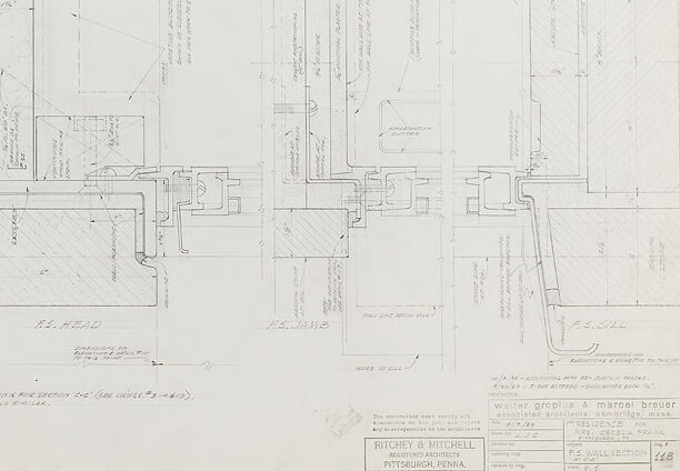
This image is a detailed architectural blueprint. It showcases a sectional plan of a building with intricate construction details. The drawing includes multiple cross-sections, each meticulously labeled with measurements, materials, and structural components. There is a clear emphasis on the precise dimensions and specifications necessary for construction, including wall thicknesses, window placements, and foundation details. Various technical annotations and notes are handwritten across the blueprint, providing additional instructions and clarifications pertinent to the construction process. The bottom right corner of the drawing includes a title block, which identifies the architects and engineers responsible for the design. The firms "Ritchey & Mitchell" and "Marcel Breuer and Associates" are credited, along with their location in Pittsburgh, Pennsylvania. The careful organization and detailed annotations suggest that this blueprint is intended for use by builders and contractors to accurately construct the building as designed by the architects.
Anthropic Claude
Created by claude-3-haiku-20240307 on 2024-12-30
The image appears to be an architectural or engineering blueprint or schematic diagram. It contains various geometric shapes, lines, and annotations that seem to represent technical details and specifications for a structure or system. The overall layout and level of detail suggest this is a technical drawing or plan, rather than an artistic or representational image.
Created by claude-3-opus-20240229 on 2024-12-30
The image appears to be a detailed architectural blueprint or floor plan sketch. It shows various rooms, walls, dimensions, and annotations for what seems to be the layout of a building or structure. The plan includes rectangular spaces of different sizes connected by doorways and passages. Measurements and technical notes are handwritten throughout the blueprint. The image has a vintage, weathered appearance with grid lines and faded text, suggesting it may be an older architectural drawing or planning document from an earlier era of building design and construction.
Created by claude-3-5-sonnet-20241022 on 2024-12-30
This appears to be an architectural or engineering technical drawing, specifically a detailed floor plan or section drawing. The image is primarily in black and white/grayscale and shows various lines, measurements, and technical notations. There are cross-sections of what appear to be walls, doorways, or structural elements, with detailed dimensions and specifications marked throughout. The drawing has a title block in the lower right corner, which is typical of professional architectural drawings. The style and format suggests this is likely a construction document or building specification drawing, possibly from a commercial or institutional project. The level of detail and professional presentation indicates this was created by an architectural or engineering firm.
Meta Llama
Created by us.meta.llama3-2-11b-instruct-v1:0 on 2025-03-16
The image presents a technical drawing of a mechanical device, likely a machine part or assembly, created by Ritchey & Mitchell Engineering Works in Pittsburgh, Pennsylvania. The drawing is rendered in black ink on white paper and features a detailed, technical representation of the device's components and their relationships. **Key Features:** * **Device Description:** The device appears to be a complex mechanical assembly, comprising multiple parts and components. * **Technical Details:** The drawing includes various technical details, such as dimensions, tolerances, and material specifications. * **Ritchey & Mitchell Engineering Works:** The company's name and location are prominently displayed in the bottom-right corner of the drawing. * **Date:** Although the exact date of the drawing is not specified, it is likely from the early 20th century, given the style and content of the drawing. **Purpose:** The purpose of this technical drawing is to provide a detailed, accurate representation of the device's design and construction. It would have been used by engineers, manufacturers, and other stakeholders involved in the production and maintenance of the device. **Conclusion:** In conclusion, the image presents a detailed technical drawing of a mechanical device created by Ritchey & Mitchell Engineering Works in Pittsburgh, Pennsylvania. The drawing provides a comprehensive overview of the device's components and their relationships, making it an essential tool for engineers, manufacturers, and other stakeholders involved in the production and maintenance of the device.
Created by us.meta.llama3-2-90b-instruct-v1:0 on 2025-03-16
The image depicts a detailed architectural blueprint, showcasing the intricate design and layout of a building. The blueprint is rendered in black and white, with various lines, symbols, and notations that provide valuable information about the structure's dimensions, materials, and features. **Key Features:** * **Scale:** The blueprint appears to be drawn to scale, allowing for accurate measurements and calculations. * **Symbols and Notations:** Various symbols and notations are used throughout the blueprint to indicate different elements, such as doors, windows, walls, and electrical outlets. * **Dimensions:** The blueprint includes precise dimensions for each room, hallway, and feature, ensuring that the building is constructed accurately. * **Materials:** The blueprint specifies the materials to be used for construction, including wood, steel, and concrete. * **Electrical and Plumbing:** The blueprint shows the location of electrical outlets, switches, and plumbing fixtures, ensuring that these essential systems are properly installed. * **Fire Safety:** The blueprint includes features such as fire alarms, sprinkler systems, and emergency exits, prioritizing fire safety and compliance with building codes. **Conclusion:** This architectural blueprint provides a comprehensive overview of the building's design and construction requirements. Its level of detail ensures that the building is constructed safely, efficiently, and in accordance with local building codes and regulations.
Amazon Nova
Created by amazon.nova-pro-v1:0 on 2025-02-27
The image is a technical drawing of a building's floor plan, specifically the second floor, as indicated by the label "2nd Floor." The drawing is presented in black and white, typical of architectural blueprints. It includes various sections and annotations that provide detailed information about the layout, dimensions, and structural elements of the floor. The plan shows different rooms and areas, including a kitchen, dining room, living room, bedrooms, and bathrooms. There are also details about the placement of windows, doors, and staircases. The drawing includes measurements and notes that are essential for construction and design purposes.
Created by amazon.nova-lite-v1:0 on 2025-02-27
The image is a blueprint of a building, showing a detailed layout of the structure. The blueprint includes various sections, including floor plans, elevation views, and structural details. The blueprint is labeled with measurements, dimensions, and annotations, indicating the specific dimensions and locations of various elements within the building. The blueprint is likely used for construction purposes, providing a clear and precise guide for builders and architects to follow during the construction process.
Text analysis
Amazon