Machine Generated Data
Tags
Color Analysis
Feature analysis
Amazon
| Document | 61.1% | |
Categories
Imagga
| text visuals | 100% | |
Captions
Microsoft
created on 2018-03-22
| a close up of text on a white background | 82.4% | |
| a close up of text on a black background | 77.8% | |
| a close up of text on a white surface | 77.7% | |
OpenAI GPT
Created by gpt-4o-2024-05-13 on 2025-03-07
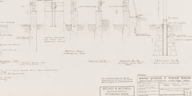
This image shows an architectural drawing containing several detailed sectional views of a structure's construction elements. The drawing includes multiple sections labeled as Section F-F, Section E-E, Section C-C, Section D-D, Section B-B, and Section A-A from left to right. Each section features annotations, measurements, and notes detailing the components and materials used in the structure, such as footing, posts, beams, reinforcement details, and different layers from the foundation up to the roof level. At the bottom right corner, there is a title block which identifies the architects and the project details. Specifically, the title block lists Ritchey & Mitchell as the associated architects from Pittsburgh, Pennsylvania, and revisions by Walter Gropius & Marcel Breuer from Cambridge, Massachusetts. Additional information within the title block includes the project name, noting that the drawing is for the 'S.F. Enthoven House' with details such as project number, sheet number, and date. The drawing is a detailed and technical representation, likely intended for use in the construction and verification of the specified sections of the structure.
Created by gpt-4 on 2025-03-07
The image displays a set of architectural plans or technical drawings that exhibit various sections of a building or a structure. These plans are detailed, showing measurements and construction notes that guide the building process or the fabrication of specific architectural elements. The drawing is made with precision, using straight lines for the outlines of the structure and annotations to explain the details. The sections appear to correspond to different parts of a building, as indicated by titles such as "Section A-A" or "Section B-B," and common architectural terms can be seen, like "Concrete Slab" and "Ground." The drawing style suggests that this is a professional document, likely used in the construction industry by architects, engineers, or builders. There is a title block in the lower-right corner, which traditionally provides information about the drawing, such as the project name, the names of the architects, draughtsperson, date, and revision history. In this title block, the names "Gropius & Marcel Breuer" appear, possibly referring to the famous Bauhaus architects. The drawing is labeled with the firm name "Ritchie & Mitchell" from Pittsburgh, Pennsylvania, and includes specifics like drawing number, date, and other project information. Although this image is not fully legible due to the resolution, the details suggest the professional and diligent nature of architectural design work.
Anthropic Claude
Created by claude-3-haiku-20240307 on 2024-12-31
The image appears to be a technical drawing or blueprint showing various cross-sectional views and details of an architectural or engineering structure. The drawing contains detailed technical specifications, measurements, and annotations. It appears to be a design or schematic plan for some kind of structural or mechanical system, though without more context I cannot determine the specific purpose or application of the design.
Created by claude-3-opus-20240229 on 2024-12-31
The image shows architectural blueprints or plans for a building called "Walter Steckler & Marcel Breuer, Associated Architects". It includes cross-section views from different angles showing the structural details and dimensions of columns, beams, footings and other architectural elements. The plans are precisely drawn with thin lines on a light colored background. Handwritten notes and callouts provide additional information about the materials and specifications. A title block in the lower right corner identifies this as a set of plans for the "Ritchey & Mitchell Residence" in Pittsburgh, Pennsylvania by the aforementioned architects.
Created by claude-3-5-sonnet-20241022 on 2024-12-31
This image appears to be an architectural drawing showing various section details and construction specifications. It's a technical drawing with multiple cross-sectional views labeled as "SECTION F-F," "SECTION C-C," "SECTION D-D," "SECTION B-B," and "SECTION A-A." The drawing includes detailed measurements and construction notes, and appears to be done in a professional architectural drafting style. At the bottom of the drawing, there are credits showing it was created by Walter Gropius & Marcel Breuer, who were prominent modernist architects. The drawing was prepared for Ritchey & Mitchell in Pittsburgh, Pennsylvania. The sections show various structural details including footings, wall connections, and other construction elements. The drawing is primarily in black and white/grayscale and includes detailed annotations and dimensions typical of architectural construction documents.
Meta Llama
Created by us.meta.llama3-2-11b-instruct-v1:0 on 2025-03-14
The image presents a detailed architectural drawing, likely created by Walter Gropius and Marcel Breuer, showcasing their design for a building. The drawing is a technical representation of the structure's layout, featuring various sections and elevations. **Key Features:** * **Title Block:** Located in the bottom-right corner, the title block contains essential information about the drawing, including the architects' names, the client's name, and the date. * **Drawing Scale:** The drawing scale is indicated in the bottom-right corner, providing a clear understanding of the proportionate size of the building. * **Sectional Drawings:** The drawing includes several sectional drawings, which are detailed representations of specific parts of the building. These sections provide a comprehensive understanding of the building's internal structure and layout. * **Elevations:** The drawing also features elevations, which are detailed representations of the building's exterior. These elevations show the building's facade, including windows, doors, and other architectural features. * **Notes and Annotations:** Throughout the drawing, there are numerous notes and annotations that provide additional information about the design. These notes may include comments from the architects, engineers, or other stakeholders involved in the project. * **Grid Lines:** The drawing features grid lines, which help to organize the layout and provide a clear understanding of the building's proportions. * **Scale Bars:** Scale bars are used to indicate the scale of the drawing, allowing the viewer to understand the proportionate size of the building. * **Legend:** A legend is included in the drawing, which explains the symbols and abbreviations used throughout the drawing. This helps to ensure that the viewer can accurately interpret the information presented. **Overall Impression:** The drawing exudes a sense of professionalism and attention to detail, reflecting the expertise and skill of the architects involved. The use of clear labels, legends, and annotations ensures that the viewer can easily understand the information presented. The drawing provides a comprehensive overview of the building's design, making it an essential tool for architects, engineers, and other stakeholders involved in the project.
Created by us.meta.llama3-2-90b-instruct-v1:0 on 2025-03-14
The image presents a detailed architectural drawing of a building's cross-section, showcasing various components and features. The drawing is rendered in black ink on white paper, with handwritten notes and labels providing additional information. **Key Features:** * **Sectional Views:** The drawing includes multiple sectional views of the building, each highlighting different aspects of its design and construction. * **Labels and Notes:** Handwritten labels and notes are scattered throughout the drawing, offering insights into the building's materials, dimensions, and other relevant details. * **Architectural Details:** The drawing showcases various architectural elements, such as walls, windows, doors, and rooflines, which are carefully rendered to provide a clear understanding of the building's design. * **Scale and Proportions:** The drawing appears to be drawn to scale, with precise measurements and proportions that allow for accurate analysis and interpretation. * **Signature Block:** A signature block is visible in the bottom-right corner of the drawing, indicating that it was created by Walter Gropius and Marcel Breuer, two renowned architects. **Overall Impression:** The image presents a meticulous and detailed architectural drawing that showcases the building's design and construction. The use of handwritten notes and labels adds a personal touch, while the signature block provides a sense of authenticity and credibility. The drawing's level of detail and precision suggests that it was created for a specific purpose, such as a construction project or a design competition.
Amazon Nova
Created by amazon.nova-lite-v1:0 on 2025-02-26
This image appears to be a technical drawing or blueprint of a building or structure. The drawing shows various sections and details of the structure, including: - Sections A-A, B-B, C-C, and D-D, which depict different views and elevations of the building. - Dimensions and measurements in feet and inches, indicating the scale and size of the structure. - Notes and annotations providing additional information about the design and construction. The drawing is labeled as "Walter Gropius and Marcel Breuer, Associated Architects, Cambridge, Mass." This suggests that the building or structure was designed by the renowned architects Walter Gropius and Marcel Breuer, who were associated with the Bauhaus school of design. The drawing also includes the name "Ritchey & Mitchell," which may be the engineering or construction firm responsible for the project. The location is listed as "Pittsburgh, Pennsylvania," indicating that the building or structure was likely constructed in that area. Overall, the image appears to be a technical drawing or blueprint used in the design and construction of a building or structure, providing detailed information about its dimensions, sections, and other relevant details.
Created by amazon.nova-pro-v1:0 on 2025-02-26
The image is a black-and-white architectural drawing, likely a blueprint, of a building structure. The drawing is divided into several sections, each labeled with letters such as "A," "B," "C," and "D." Each section contains detailed architectural plans, including dimensions, material specifications, and structural elements. The sections are interconnected, showing how the different parts of the building fit together. The drawing also includes notes and annotations, providing additional information about the construction process and materials used. The overall layout suggests a complex building with multiple levels and intricate design features.
Text analysis
Amazon