Machine Generated Data
Tags
Color Analysis
Categories
Imagga
| text visuals | 99.6% | |
| paintings art | 0.3% | |
Captions
Microsoft
created on 2018-03-22
| a close up of text on a white background | 76.3% | |
| a close up of text on a white surface | 74% | |
| a close up of text on a black background | 69.6% | |
OpenAI GPT
Created by gpt-4 on 2025-03-05
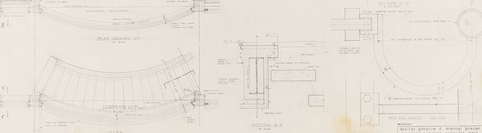
The image is a technical drawing or architectural blueprint, showcasing a series of detailed plans and cross-sections for a construction project. These drawings typically provide precise dimensions, construction methods, and material specifications which are used to guide the building process. The layout includes multiple views of components, with labels and annotations explaining specific parts and measurements. The drawing seems to be executed in pencil on a large sheet of paper, a common practice before the widespread use of computer-aided design (CAD) software. The technical drawing contains annotations, measurements, and is composed of various cross-sectional views (labeled Section A-A, B-B, C-C, etc.), each detailing different parts or aspects of the design. Different types of lines represent various textures, materials, and boundaries. In the bottom right corner, there is additional text which likely includes the project name, address or location, the names of the architect or engineer, the client, and possibly a date when the drawing was completed or revised.
Created by gpt-4o-2024-05-13 on 2025-03-05
The image shows a detailed architectural drawing or blueprint. The drawing includes various sections, plans, and elevations of a building or structure, focusing on specific construction details and elements. The annotations and measurements are written in pencil, providing detailed information for each part of the design. Key features include: - Different sections labeled as Section Thru Sill, Section Thru Head, Section B-B', Section C-C', Section A-A', and a plan view labeled as "Plan Locating BP." - Dimensions and notes describing materials, construction techniques, and assembly instructions. - Curved and straight sections indicating specific parts of the structure, such as walls, sills, and possibly a balustrade or similar building feature. - The title block in the lower right-hand corner, which contains details about the project, including the architects' names "Walter Gropius & Marcel Breuer," and information about the associated architectural firm, "Architects & Associates" from Cambridge, Mass. There is also a date, "5-10-1938," and a project number or reference. Overall, the drawing appears to focus on detailed construction aspects of a specific architectural project planned or designed by the renowned architects Walter Gropius and Marcel Breuer.
Anthropic Claude
Created by claude-3-haiku-20240307 on 2024-12-30
This image appears to be an architectural or engineering drawing or schematic. It contains various technical diagrams, plans, and detailed schematics of different components or structures. The drawing includes measurements, labels, and technical annotations. Overall, this seems to be a detailed technical drawing or blueprint of some kind of engineering or construction project, though I cannot identify any specific individuals or entities depicted in the image.
Created by claude-3-opus-20240229 on 2024-12-30
The image shows a technical drawing or blueprint of a floor plan for a building. It contains detailed annotations, measurements, and labels indicating different sections and structural elements of the building layout. The plan shows various rooms, walls, doors, and other architectural features. At the bottom right corner, there is a title block with some text that appears to provide information about the project, such as "Walter, Ovorick & Mensch Struct." which likely refers to the architects or engineers involved. The drawing is done in black lines on a off-white or yellowish background, giving it a vintage or aged appearance typical of old blueprints or architectural plans.
Created by claude-3-5-sonnet-20241022 on 2024-12-30
This image shows a detailed architectural drawing or blueprint containing multiple technical sections and plans. The drawing includes various cross-sections, elevation views, and plan views with detailed measurements and annotations. There's a curved or arc-shaped element shown in plan view in the lower left portion of the drawing, and several detailed section cuts showing construction details. The drawing appears to be done in a professional architectural style with clean lines and proper architectural drafting conventions. At the bottom right, there appears to be a title block which is typical of architectural drawings. The overall drawing seems to be focused on specific construction or assembly details of what might be part of a larger architectural project.
Meta Llama
Created by us.meta.llama3-2-11b-instruct-v1:0 on 2025-03-12
The image displays a technical drawing of a building's floor plan, featuring various rooms and sections. The drawing is presented on a sheet of paper with a light yellowish color, indicating its age. **Key Features:** * **Floor Plan:** The drawing depicts the layout of a building's interior, including multiple rooms, corridors, and staircases. * **Sectional Views:** The drawing includes sectional views of specific areas, providing detailed information about the building's structure and design. * **Labels and Notations:** Various labels and notations are scattered throughout the drawing, likely indicating different rooms, features, and dimensions. * **Scale:** A scale is visible in the bottom-right corner of the drawing, allowing for accurate measurements and calculations. * **Authors:** The drawing is attributed to Walter Groblus and Marcel Breuer, as indicated by the text in the bottom-right corner. **Overall Impression:** The technical drawing provides a comprehensive overview of the building's design and layout, showcasing the attention to detail and precision required for architectural projects. The inclusion of sectional views and labels adds depth and clarity to the drawing, making it a valuable resource for architects, engineers, and builders.
Created by us.meta.llama3-2-90b-instruct-v1:0 on 2025-03-12
This image is a blueprint for a building, featuring various sections and details. The blueprint is drawn in pencil on a white background, with several sections labeled "SECTION THRU ELL," "SECTION A-A," and "SECTION C-C." Each section provides a detailed view of the building's design, including walls, windows, doors, and other architectural features. The blueprint also includes notes and measurements, written in pencil, which provide additional information about the building's construction. The overall design of the building appears to be modern and sleek, with clean lines and minimal ornamentation. In the bottom-right corner of the image, there is a small box with text that reads "Walter Gropius & Marcel Breuer" and "Associates Architects Cambridge Mass." This suggests that the blueprint was created by the renowned architects Walter Gropius and Marcel Breuer, who were known for their innovative and influential designs in the early 20th century. Overall, this image provides a fascinating glimpse into the design process of a building, showcasing the attention to detail and precision required to bring a architectural vision to life.
Amazon Nova
Created by amazon.nova-lite-v1:0 on 2025-01-11
This image depicts a set of architectural blueprints for a building. The blueprints are divided into several sections, each providing different perspectives and details of the structure. The top section shows a floor plan with various rooms and their dimensions. The middle section includes cross-sections of the building, illustrating the internal structure and layout. The bottom section features a detailed plan looking down from above, highlighting the roof structure and its components. The blueprints are labeled with section names and measurements, indicating a precise and professional approach to the architectural design. The overall layout suggests a modern and functional building, possibly a residential or commercial space.
Created by amazon.nova-pro-v1:0 on 2025-01-11
The image is a technical drawing, possibly an architectural or engineering plan, presented on a white background. The drawing is divided into several sections, each labeled with a letter and a number, such as "SECTION A-A" and "SECTION C-C". Each section appears to represent different views or details of a structure. The drawings include lines, dimensions, and annotations, which are typical in technical drawings to convey specific information about the design. There are also notes and labels that provide additional details about the components and measurements. The overall layout suggests a methodical approach to detailing the structure's components and their relationships.
Text analysis
Amazon