Machine Generated Data
Tags
Color Analysis
Feature analysis
Amazon
| Book | 99.5% | |
Categories
Imagga
| text visuals | 100% | |
Captions
Microsoft
created on 2018-03-22
| a close up of text on a white surface | 69.4% | |
| close up of text on a white surface | 65.2% | |
| a close up of text on a white background | 65.1% | |
OpenAI GPT
Created by gpt-4 on 2025-03-08
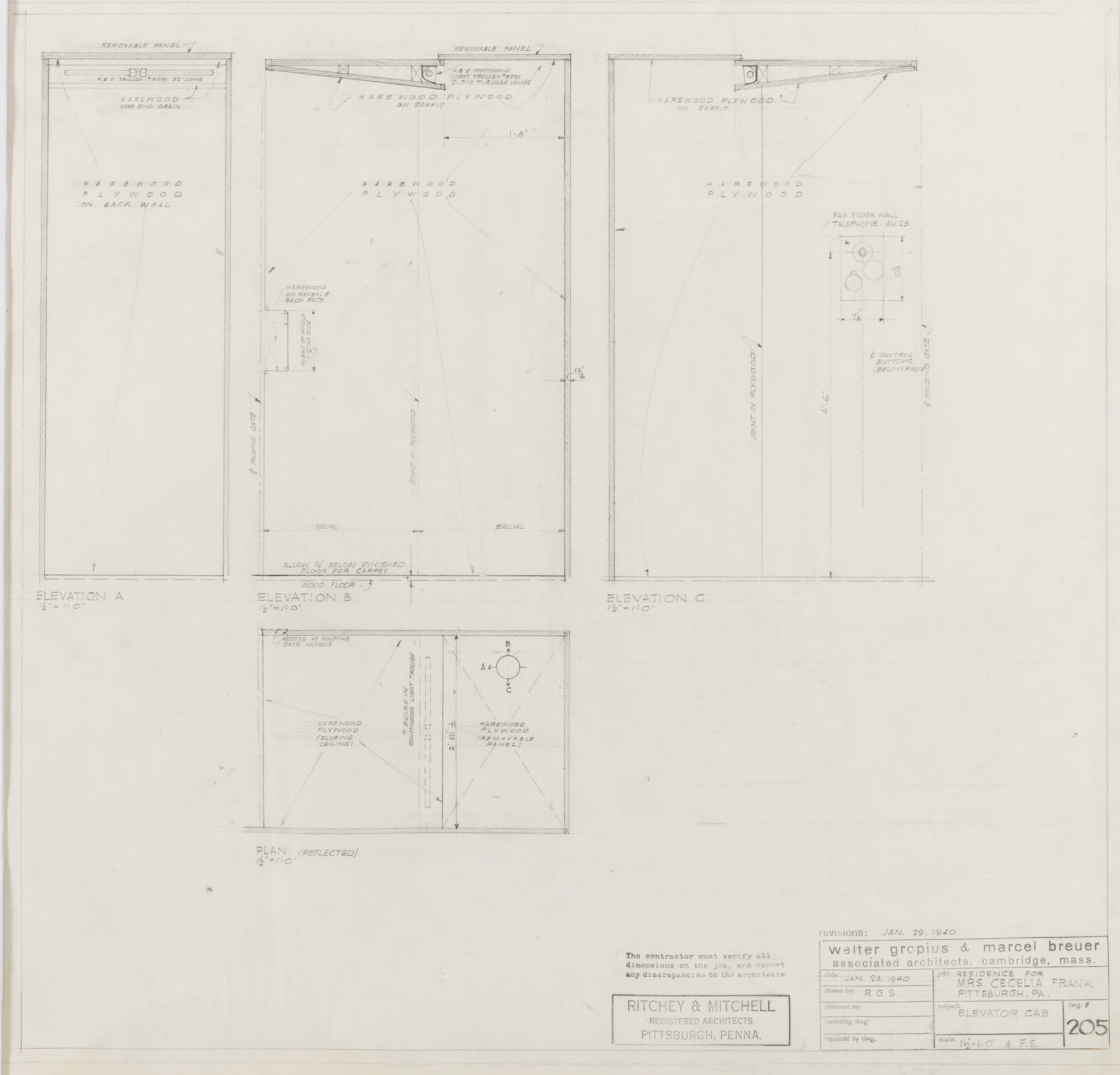
This image is an architectural drawing or blueprint featuring plans and elevations for some components of a structure or piece of furniture. The technical drawing contains several views:
- Elevation A, B, and C: These are side views of a structure or component, showing detail and specifications such as material notes (mentioning hardwood plywood, for instance) and sometimes dimensions.
- Plan (Reflected): This is a top view, or plan, of the structure or component. It is labeled as "reflected," which often means it's a mirror image of the actual plan, commonly used to view the ceiling layout from below.
There are notes and labels throughout, indicating specific materials and construction details. In the bottom right corner, there are signatures or stamps of approval from various parties involved in the process, such as "Walter Gropius & Marcel Breuer, Architects" and "Ritchey & Mitchell, Registered Architects." The drawing is also dated "JAN. 29, 1940."
These sorts of plans are essential in the construction and manufacturing process, ensuring that everyone involved has precise specifications to work from. The technical nature of the drawing suggests it is meant for professionals in the architecture, design, or building industry.
Created by gpt-4o-2024-05-13 on 2025-03-08
The image is a technical architectural drawing or blueprint titled "ELEVATOR CAB," dated January 29, 1940. This drawing includes details for the construction or assembly of an elevator cab and was created by Ritchey & Mitchell Registered Architects, based in Pittsburgh, Pennsylvania. It appears to be part of a project for "Mrs. Ceila Frank." The drawing is associated with well-known architects Walter Gropius and Marcel Breuer, as indicated in the title block at the bottom right corner.
The blueprint includes four primary views:
- Elevation A
- Elevation B
- Elevation C
- A plan view (noted as "Plan" with the word "(Reversed)" beneath it)
Each elevation view provides measurements and construction details such as the use of "Wainscot Plywood" and "glue blocks." For example, Elevation B describes the installation of a "Telephone Alcove" as well as details about the ash or birch finish. The plan view includes notations about specific dimensions and placement of panels and fixtures within the elevator cab.
Additional annotations provide details for the contractor, including the requirement to verify all dimensions on the job and instructions regarding panel removal. There are also specific notes regarding the materials and finishes to be used.
Overall, the blueprint is a meticulous and detailed guide for constructing an elevator cab, featuring precise measurements and specifications typical of architectural and engineering documents from the mid-20th century.
Anthropic Claude
Created by claude-3-haiku-20240307 on 2024-12-30
This image appears to be an architectural blueprint or technical drawing. It contains several elevations or side views of what seems to be a structure or piece of equipment, along with some associated technical details and dimensions. The drawing provides detailed specifications and measurements, but does not contain any human faces or identities.
Created by claude-3-5-sonnet-20241022 on 2024-12-30
This is an architectural drawing/blueprint showing elevator cab details from 1940. The drawing includes multiple views - three elevations (A, B, and C) and a plan view. Each elevation shows different aspects of what appears to be an elevator cab design. The drawing is quite detailed with precise measurements and specifications, drawn to scale. At the bottom of the sheet, there are title blocks indicating this was a project by Walter Gropius & Marcel Breuer, Associated Architects from Cambridge, Massachusetts, with Ritchey & Mitchell of Pittsburgh, Pennsylvania as consulting architects. The drawing is numbered 205 and dated January 29, 1940. The project appears to be for an elevator cab, possibly for a residential project. The drawings are primarily line work in black on a light background, showing various technical details of the elevator cab construction.
Meta Llama
Created by us.meta.llama3-2-11b-instruct-v1:0 on 2025-03-15
The image presents a technical drawing of an elevator cab, comprising multiple views and details. The drawing is rendered in pencil on white paper, with the following key elements:
- Title: The title "RITCHIE & MITCHELL" is displayed in the bottom-left corner, accompanied by the text "REGISTERED ARCHITECTS PITTSBURGH, PENNA." in smaller letters below.
- Date: The date "JAN. 29, 1940" is inscribed in the bottom-right corner, along with the names "WALTER GROPIUS & MARCEL BREUER" and "ASSOCIATED ARCHITECTS CAMBRIDGE, MASS."
- Elevator Cab Details: The drawing includes various views of the elevator cab, including:
- Front elevation
- Rear elevation
- Side elevation
- Plan view
- Sectional view
- Dimensions: The drawing includes dimensions for each view, providing precise measurements for the elevator cab's design.
- Notes: The drawing includes notes and annotations, likely indicating specific design requirements or considerations for the elevator cab's construction.
Overall, the image provides a detailed technical drawing of an elevator cab, showcasing its design and dimensions. The inclusion of the architects' names and the date suggests that this drawing may be a part of a larger project or design portfolio.
Created by us.meta.llama3-2-90b-instruct-v1:0 on 2025-03-15
This image presents a set of architectural drawings for an elevator, comprising four distinct sections. The top-left section is labeled "ELEVATION A," while the top-right section is labeled "ELEVATION C." The bottom-left section is labeled "ELEVATION B," and the bottom-right section appears to be a detailed view of the elevator's interior.
The drawings are rendered in black ink on white paper, with various annotations and labels throughout. The overall design suggests a focus on functionality and practicality, with clean lines and minimal ornamentation. The use of different elevations provides a comprehensive understanding of the elevator's design, allowing viewers to visualize its layout and features from multiple angles.
The image also includes a title block in the bottom-right corner, which provides information about the project, including the date, location, and architects involved. This adds context to the drawings and helps to situate them within a larger architectural project.
Overall, this image provides a detailed and informative representation of an elevator's design, showcasing the attention to detail and precision that goes into creating functional and efficient architectural spaces.
Amazon Nova
Created by amazon.nova-lite-v1:0 on 2025-01-12
The image is a technical architectural drawing, likely a floor plan or elevation, created by the architectural firm Walter Gropius & Marcel Breuer. The drawing is dated January 29, 1940, and is associated with the residence of Mrs. Cecelia Frank in Pittsburgh, Pennsylvania. The drawing contains various sections, including:
A removable panel section with details about the materials used, such as plywood and hardware.
Elevation views labeled as "Elevation A," "Elevation B," and "Elevation C," showing different perspectives of the structure.
A plan view labeled as "Plan (Reflected)" showing the layout of the space.
The drawing includes dimensions and notes, such as "ALLOW 1/4 BELOW FINISHED FLOOR FOR CARPET" and "FAR FLYER WALL TELEPHONE AM 25."
The drawing is signed by R.G.S. and includes a revision date of January 23, 1940.
The document is stamped with the name of the architectural firm, "WALTER GROPIUS & MARCEL BREUER, ASSOCIATED ARCHITECTS, CAMBRIDGE, MASS."
The drawing is part of a larger set, indicated by the number "205" in the bottom right corner.
This architectural drawing is a technical representation of a residential structure, likely providing detailed information for construction and design purposes.
Created by amazon.nova-pro-v1:0 on 2025-01-12
The image is a blueprint or architectural drawing that appears to be a detailed plan for a construction project. The document is divided into sections with labels such as "ELEVATION A," "ELEVATION B," and "ELEVATION C," which likely refer to different views or levels of the structure.
The drawing includes technical details such as dimensions, material specifications (e.g., plywood, hardwood), and construction notes. There are also annotations indicating revisions and dates, suggesting that the plan has undergone changes over time.
The bottom right corner contains a table with additional information, possibly related to the project's specifications or requirements. The names "Walter Gropius & Marcel Breuer" are mentioned, indicating the architects or designers involved in the project.
Overall, the image represents a comprehensive architectural plan for a construction project, with detailed instructions and specifications for the builders or contractors.
Text analysis
Amazon