Machine Generated Data
Tags
Color Analysis
Feature analysis
Amazon
Clarifai
AWS Rekognition
| Book | 56.2% | |

Categories
Imagga
created on 2018-03-22
| paintings art | 63.6% | |
| text visuals | 35.5% | |
| streetview architecture | 0.7% | |
| interior objects | 0.1% | |
| food drinks | 0.1% | |
| beaches seaside | 0.1% | |
Captions
Microsoft
created by unknown on 2018-03-22
| a close up of text on a white surface | 70.5% | |
| a close up of text on the side of a building | 60.7% | |
| a close up of text on a building | 60.6% | |
Clarifai
No captions written
Salesforce
Created by general-english-image-caption-blip on 2025-05-11
a photograph of a drawing of a map of a city
Created by general-english-image-caption-blip-2 on 2025-06-28
a drawing of a building with a plan and drawings
OpenAI GPT
Created by gpt-4 on 2024-12-16
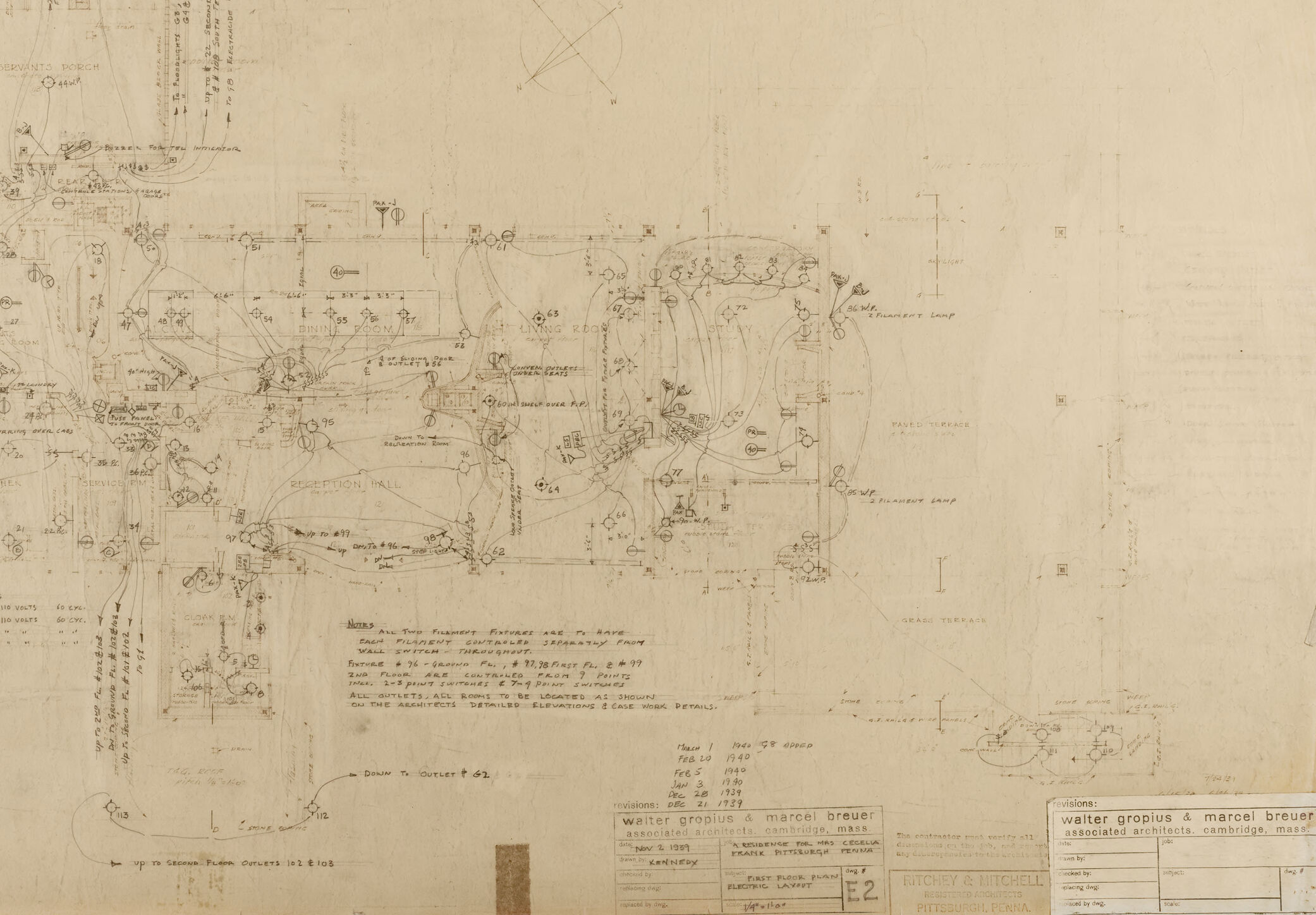
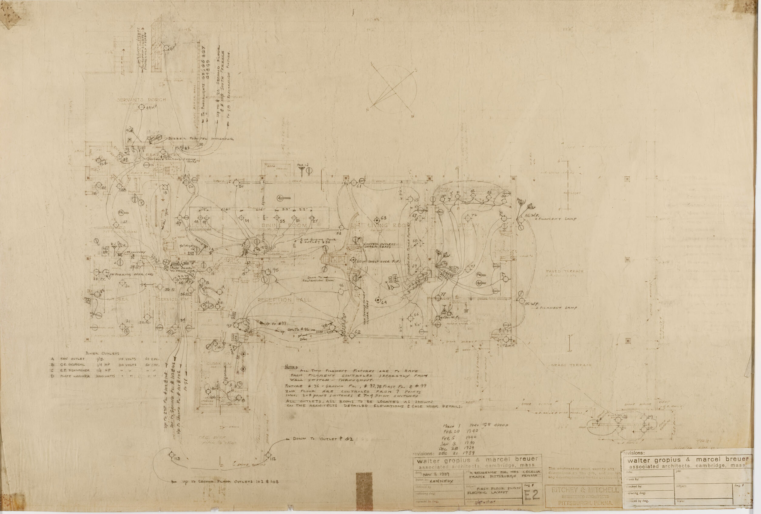
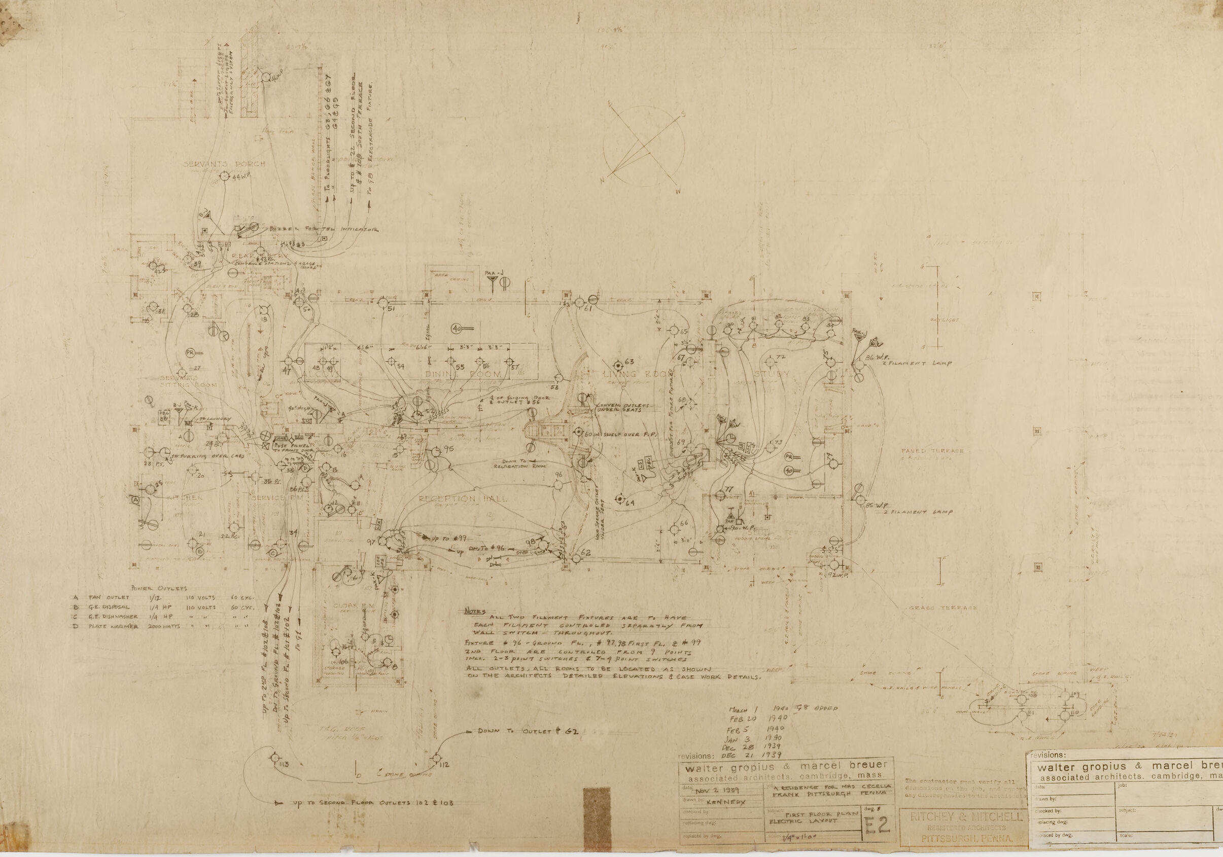
This image appears to be a detailed architectural drawing or blueprint of a building plan. The plan includes numerous annotations, dimensions, and details that suggest the design of an intricate structural layout. There are various rooms and spaces labeled, indicating the function of each area. Various lines and circles represent the architectural design and spatial arrangement of the structure, and there's a technical legend explaining symbols and abbreviations used within the drawing.
Text blocks and revision notes indicate modifications made to the design over time, signifying an evolving plan. The drawing has a faded, aged appearance, typical for architectural blueprints that have been handled and referenced over time. The names Walter Gropius & Marcel Breuer, prominent figures in modern architecture, are visible, which associates this drawing with their work or influence. The drawing is not only a practical tool for construction but also an artifact of architectural history.
Created by gpt-4o-2024-05-13 on 2024-12-16
This image depicts an architectural engineering drawing or plan. The plan is detailed with various annotations, measurements, and symbols indicating different aspects of the design, likely related to electrical or lighting systems in a building.
Key features include:
- Multiple rooms labeled such as "Reception Hall," "Dining Room," and "Living Room."
- Symbols and lines that seem to indicate wiring paths or circuits.
- A legend at the bottom left with notes and instructions regarding different elements, such as points for various outlets (TV, convenience outlets, ceiling light, floor warmer, etc.).
- A compass rose indicating directions (North, South, East, West).
- Specific details about revisions, dates, and the involved architectural firms. Notably, the names “Walter Gropius & Marcel Breuer” are mentioned, indicating their involvement in the design.
- Detailed technical notes and specifications, likely meant for contractors or engineers working from this plan.
The plan appears to be a vintage, hand-drawn document, showing signs of age and wear, such as faded ink and creases.
Anthropic Claude
Created by us.anthropic.claude-3-5-sonnet-20241022-v2:0 on 2025-06-24
This appears to be an architectural or engineering drawing/sketch from Walter Gropius & Marcel Breuer, as indicated by the title block at the bottom of the image. The drawing is on aged, yellowed paper and shows what appears to be a site plan or layout drawing with various symbols, notations, and lines scattered across the page. The drawing style is technical and schematic in nature, with various geometric shapes, connecting lines, and annotations throughout. The sketch appears to be from around 1939 based on the information visible in the title block. The drawing has a somewhat faded quality typical of historical architectural documents from this era.
Created by claude-3-haiku-20240307 on 2024-12-16
This appears to be an architectural or engineering diagram or schematic, containing various technical drawings, calculations, and annotations. The image is predominantly made up of intricate line work, geometric shapes, and notations, suggesting it is some kind of technical plan or diagram rather than a representational image. There are no human faces or figures visible in this image.
Created by claude-3-5-sonnet-20241022 on 2024-12-16
This appears to be an architectural or technical drawing/blueprint, rendered in a sketchy, schematic style. It shows what seems to be a complex layout or floor plan with numerous interconnected elements, notations, and symbols scattered throughout. The drawing has a compass rose indicating directional orientation and contains various annotations and measurements. At the bottom of the image, there are title blocks and what appear to be architectural firm stamps or labels. The overall drawing has a vintage or aged appearance, with a sepia or yellowish tone to the paper. The layout appears quite intricate with multiple curved lines, circles, and geometric shapes connected by various pathways or lines.
Meta Llama
Created by us.meta.llama3-2-11b-instruct-v1:0 on 2024-12-16
The image presents a detailed technical drawing of an engine, likely created by Walter Gropius and Marcel Breuer. The drawing is rendered in pencil on a yellowed paper, with various symbols, lines, and notations that suggest it is a precise and intricate design.
- Engine Design
- The engine is depicted in a complex configuration, with multiple components and systems interconnected.
- The drawing includes labels and annotations, indicating the various parts and their functions.
- The engine appears to be a high-performance design, with a focus on efficiency and power output.
- Technical Details
- The drawing includes technical specifications and measurements, such as dimensions, tolerances, and material properties.
- The notation system used in the drawing suggests a high level of precision and attention to detail.
- The technical details provided in the drawing would be essential for manufacturing and assembly purposes.
- Designers' Signatures
- The signatures of Walter Gropius and Marcel Breuer are visible in the bottom-right corner of the drawing.
- The signatures indicate that the designers were responsible for the creation of the engine design.
- The inclusion of the designers' signatures adds authenticity and credibility to the drawing.
- Context
- The drawing is likely from the early 20th century, given the style and notation system used.
- The engine design may have been intended for use in a specific industry or application, such as aviation or automotive.
- The drawing provides valuable insight into the design process and technical capabilities of the time.
In summary, the image presents a detailed and technical drawing of an engine, created by Walter Gropius and Marcel Breuer. The drawing includes complex configurations, technical specifications, and designers' signatures, providing valuable insight into the design process and technical capabilities of the time.
Created by us.meta.llama3-2-90b-instruct-v1:0 on 2024-12-16
The image depicts a blueprint or technical drawing of a building's electrical system, likely created by Walter Gropius and Marcel Breuer. The drawing is rendered in black ink on a yellowed paper background, with various symbols, lines, and notations that represent different components of the electrical system.
Key Features:
- Symbols and Notations: The drawing features a range of symbols and notations that correspond to specific electrical components, such as switches, outlets, and wiring.
- Lines and Connections: The lines and connections between the symbols indicate the flow of electricity throughout the building.
- Scale and Proportions: The drawing appears to be scaled to represent the actual dimensions of the building and its electrical system.
- Annotations and Labels: The drawing includes annotations and labels that provide additional information about the electrical system, such as the location of circuit breakers and the type of wiring used.
Overall Impression:
The image provides a detailed and technical representation of a building's electrical system, showcasing the complexity and intricacy of modern electrical design. The use of symbols, lines, and notations creates a visually engaging and informative diagram that would be useful for architects, engineers, and electricians working on similar projects.
Amazon Nova
Created by amazon.nova-lite-v1:0 on 2025-02-26
The image is a scanned page of a technical document, possibly an architectural blueprint or engineering schematic. The document is filled with intricate line drawings, symbols, and annotations. It appears to be a detailed plan, possibly for a building or a mechanical system. The drawing is predominantly in black ink on a light-colored paper, with some areas showing signs of wear or aging. The document includes various sections with labels, measurements, and notes, indicating a complex and detailed design process. The overall impression is of a highly technical and specialized document, likely used by professionals in architecture or engineering.
Created by amazon.nova-pro-v1:0 on 2025-02-26
The image is a technical drawing, likely an architectural or engineering plan. It features a detailed layout with various components and annotations. The drawing is on a beige-colored paper with a slightly aged appearance, suggesting it might be from an older document. The plan includes a grid system with coordinates, indicating precise measurements and locations of different elements. There are several sections labeled with letters and numbers, possibly referring to different rooms or areas within a building. The drawing also contains a mix of handwritten notes and printed text, providing additional information about the plan.
Google Gemini
Created by gemini-2.0-flash-lite on 2025-05-25
This is a technical drawing, most likely an architectural plan. It's drawn on a large, aged piece of paper that looks like it may be tracing paper or similar. The lines are thin and drawn in what appears to be pencil or a similar drawing medium.
Key features and elements visible in the drawing:
- Complex Diagram: The drawing contains an intricate network of lines, circles, and symbols, suggesting a plan of something with interconnected elements, perhaps an electrical or plumbing diagram.
- Room Names: The diagram labels several rooms such as "RECEPTION HALL," "SERVANTS' BEDS," "LIVING ROOM," which suggests it is a plan of a building.
- Annotations and Legends: The drawing includes handwritten notes, dimensions, and symbols to further clarify the elements and relationships within the plan.
- Compass Rose: There is a compass rose in the top center to denote the cardinal directions (N, S, E, W).
- Title Block: At the bottom right there is a title block with the architects' names "walter gropius & marcel breuer, associated architects, cambridge mass" and the title "FIRST FLOOR PLAN ELECTRIC LAYOUT"
- Date and Revisions: There is a list of dates and revisions listed on the right side.
Overall, the image is a detailed architectural or engineering diagram, most likely a first-floor plan detailing an electrical layout. The style of drawing suggests it is a vintage plan.
Created by gemini-2.0-flash on 2025-05-25
The image shows a detailed architectural diagram, likely an electrical plan, with numerous hand-drawn annotations, symbols, and textual notes. The layout includes notations for various rooms like "Reception Hall", "Living Room", "Servants' Porch", and "Dining Room", indicating the floor plan's layout. The complex network of lines and symbols likely represents electrical circuits, outlet locations, and other related infrastructure details.
There are sections with textual information, including a note section, revision dates (e.g., Mar 1, Feb 1, Jan 5, Feb 5, Dec 21, all in 1940, and Nov 6, 1939), and the names of the architects: "Walter Gropius & Marcel Breuer, associated architects, Cambridge, Mass." The diagram is labeled as "First Floor Plan, Electric Layout," and includes a reference number "E2." Additionally, there is the mention of "Ritchey & Mitchell, Pittsburgh, Penna."
Overall, the image portrays a historical architectural document, providing insight into the design and technical specifications of a building's electrical system. The document appears aged, as seen by the yellowed paper and the manual drafting techniques.
Mistral Pixtral
Created by us.mistral.pixtral-large-2502-v1:0 on 2025-05-30
The image appears to be a detailed technical drawing, likely a blueprint or schematic, for a complex mechanical system. Here are some key observations:
Layout and Design:
- The drawing is intricate, featuring numerous components interconnected by lines, which likely represent mechanical parts, pipes, wires, or conduits.
- The design includes various symbols and annotations, indicating different types of components and their functions.
Components:
- The drawing includes a variety of mechanical elements such as valves, pumps, motors, and possibly control systems.
- There are labels and notes scattered throughout the drawing, providing specific details about each component and its function.
Annotations:
- The drawing includes handwritten notes and annotations, which provide additional information about the system's operation, maintenance, or assembly instructions.
- There are references to specific parts and their functions, such as "pump," "motor," and "valve."
Dimensions and Measurements:
- The drawing includes dimensional information, indicating the sizes and spacing of various components.
- There are scale indicators and measurement annotations, which are crucial for accurate construction and assembly.
Authors and Date:
- The bottom right corner of the drawing includes the names "Walter Gropius" and "Marcel Breuer," suggesting they are the designers or engineers responsible for the drawing.
- The date "May 2, 1939" is also noted, indicating when the drawing was created.
Purpose:
- The drawing likely serves as a detailed guide for the construction, assembly, or maintenance of a mechanical system.
- It could be part of a larger project, such as an industrial machine, a building's mechanical system, or a specialized piece of equipment.
Overall, the image is a detailed and complex technical drawing that provides comprehensive information about a mechanical system, including its components, dimensions, and operational details.
Qwen
Created by Qwen/Qwen2.5-VL-7B-Instruct on 2025-07-20
This image is a detailed architectural electrical layout drawing. It appears to be a hand-drawn plan, likely created in the early to mid-20th century, given the style and the use of textual annotations. The drawing includes various rooms and spaces such as a servants' porch, kitchen, reception hall, and living areas. It shows the layout of electrical components including outlets, fixtures, and switches. There are annotations and labels indicating the types of electrical outlets and their specifications, such as power outlets, fan outlets, and other appliances. The drawing also includes notes and revisions, dated from 1939 to 1940, which are part of a documented process for the design and construction of the electrical system for a building. The bottom of the drawing includes credits to the architects, Walter Gropius and Marcel Breuer, and the project details are for a residence for Mrs. Cecelia Frank in Pittsburgh, Pennsylvania.
Created by Qwen/Qwen2.5-VL-72B-Instruct on 2025-07-20
This image is an architectural blueprint or floor plan, likely for a residential building. The drawing is detailed and includes various rooms such as the kitchen, dining room, living room, study, and reception hall. The blueprint is marked with numerous annotations, measurements, and symbols indicating electrical outlets, light fixtures, and other elements. There are also handwritten notes and revisions, suggesting that this blueprint has been updated over time. The document is dated and signed by Walter Gropius & Marcel Breuer, indicating their involvement as the architects. The bottom right corner includes a stamp from Ritchey & Mitchell, registered architects from Pittsburgh, Pennsylvania. The blueprint appears to be for a first-floor plan and includes details such as the electrical layout and the rooms to be located as shown on the architects' detailed elevations and case work details.
Text analysis
Amazon