Machine Generated Data
Tags
Color Analysis
Feature analysis
Amazon
Clarifai

Clarifai
| Whiteboard | 88.2% | |
Categories
Imagga
created on 2018-03-22
| text visuals | 99.5% | |
| paintings art | 0.4% | |
Captions
Microsoft
created by unknown on 2018-03-22
| a close up of text on a whiteboard | 64.3% | |
| a close up of a whiteboard | 63.9% | |
| a screenshot of a computer | 61.7% | |
Clarifai
No captions written
Salesforce
Created by general-english-image-caption-blip on 2025-05-11
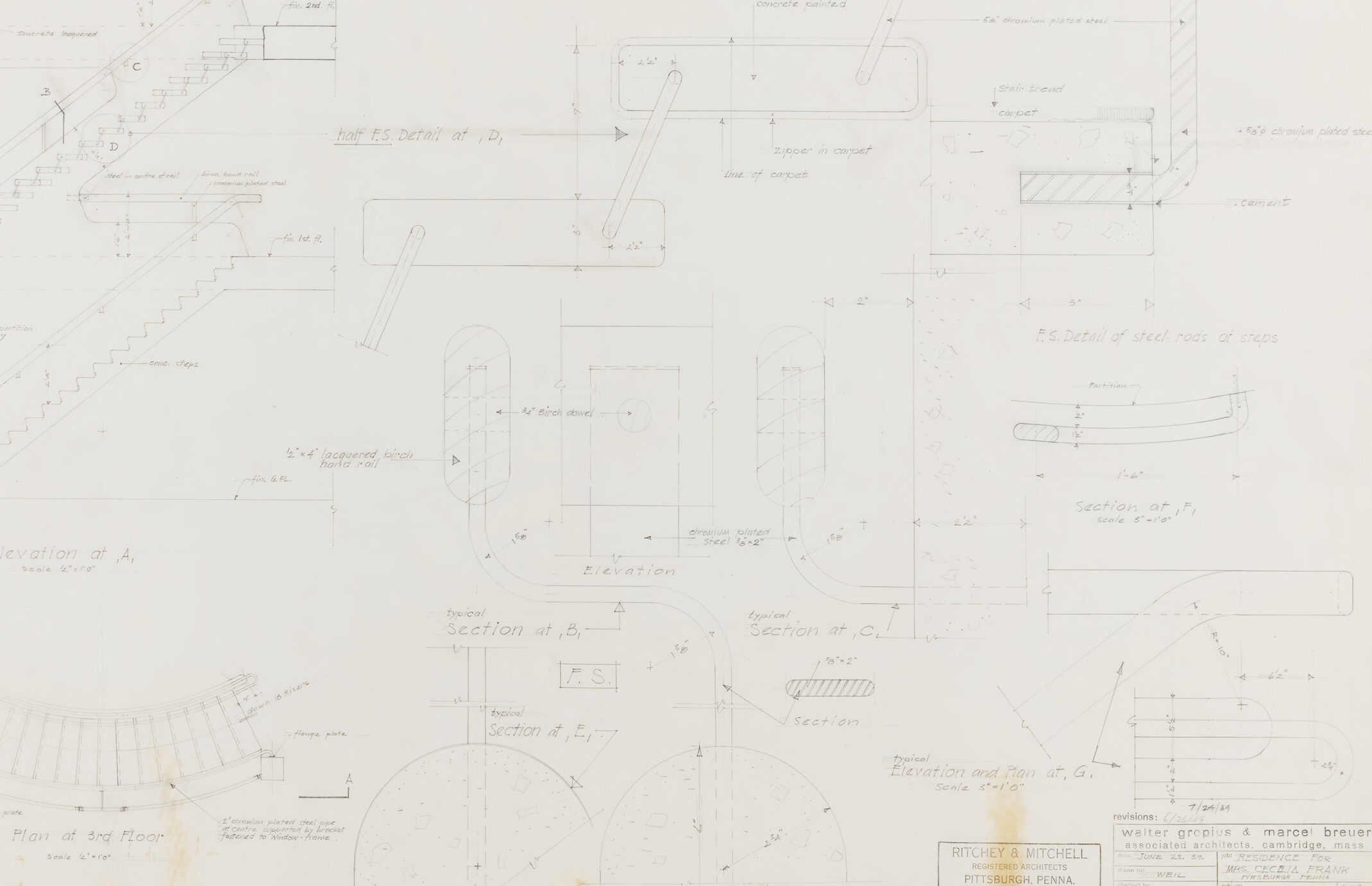
a photograph of a drawing of a plan for a staircase casement
Created by general-english-image-caption-blip-2 on 2025-06-28
a drawing of a staircase and stairs
OpenAI GPT
Created by gpt-4 on 2025-03-08
You are viewing an architectural drawing or blueprint, which consists of various detailed diagrams and plans. The image shows different sections and elevations of a construction detail, likely a part of a building. It includes staircases, sections of handrails or balustrades, and other construction elements.
Here are some specific observations:
There are labeled sections like "Elevation at A," "F.S. Detail of steel rods of steps," and "Elevation and Plan at G," suggesting detailed views of these particular components.
The drawing includes a "Plan at 3rd Floor," indicating that there is a floor plan involved, probably showing the layout or arrangement of structure at that level.
Annotations and measurements are present throughout the drawings, providing specific dimensions and instructions for construction or assembly.
The title block in the lower right corner attributes the drawing to "Ritchey & Mitchell, Pittsburgh, Penna." and indicates a collaboration with "Walter Gropius & Marcel Breuer, Associated Architects, Cambridge, Mass."
The blueprint is dated, providing historical context for the architectural work, though the specific date is not fully visible in the image.
These types of drawings are used by architects, engineers, and construction professionals to guide the building process and ensure accurate implementation of design intentions.
Created by gpt-4o-2024-05-13 on 2025-03-08
The image depicts a detailed architectural blueprint or technical drawing, likely for the construction of a building staircase and related structures. The drawing includes multiple sectional views, elevations, and detailed intricacies of elements such as handrails, steps, and supports. Specific areas in the blueprint are labeled with measurements and annotations indicating materials like steel and concrete.
Key components shown include:
- Elevation views of the staircase from different angles labeled as "Elevation at A" and other sections.
- Detailed sections of the staircase and related elements, including curves and bends in the handrail.
- Overhead plan view of the staircase at the 3rd floor level.
- Detail views of the attachment and construction techniques used for various parts of the structure.
- Dimensions and specific materials for elements such as steel rods, lacquered blocks, and plated steel are documented.
Notable labels within the drawing identify it as being associated with architects Richey & Mitchell from Pittsburgh, along with Walter Gropius & Marcel Breuer from Cambridge, Mass. Revisions and additional notes are also present in the drawing, which provide further context and instructions about the construction project.
Anthropic Claude
Created by us.anthropic.claude-3-5-sonnet-20241022-v2:0 on 2025-06-24
This is an architectural drawing or blueprint showing various technical details of what appears to be a staircase design. The drawing includes multiple views and sections, including an elevation view labeled "ELEVATION OF A," a floor plan showing curved stairs, and several detailed sections and elevations with specific measurements and annotations. The drawing contains various architectural elements like handrails, steps, and structural components shown from different angles and with precise dimensions. The document appears to be a professional architectural drawing, with title blocks and reference information visible in the bottom right corner. The drawing style is typical of mid-20th century architectural documentation, with clean lines and detailed technical specifications.
Created by claude-3-haiku-20240307 on 2024-12-30
The image appears to be an engineering or architectural blueprint containing various technical drawings and diagrams. It includes detailed sketches and measurements for different components or sections of an unidentified structure or device. The drawing style and technical specifications suggest this is likely an engineering plan or design document, although without additional context, I cannot determine the specific purpose or application of the design shown.
Created by claude-3-opus-20240229 on 2024-12-30
The image shows architectural blueprints or technical drawings. It contains various sketches, diagrams and measurements related to what appears to be the design of a building or structure. The drawings include floor plans, elevations, and detailed callouts specifying dimensions and materials. The blueprints have a worn, vintage look with yellowing of the paper. In the bottom right corner, there is a title block with project information, including the architect's name "Walter Gropius & Marcel Breuer".
Created by claude-3-5-sonnet-20241022 on 2024-12-30
This appears to be an architectural drawing or blueprint showing various technical details of what seems to be a staircase design. The drawing includes multiple views and sections, including an elevation view labeled "Elevation of A," a plan view of what appears to be a curved staircase labeled "Plan at 2nd Floor," and several detailed sections and elevations showing construction details. The drawing contains numerous measurements and annotations, and appears to be a professional architectural document. The bottom of the sheet includes what looks like a title block with architectural firm information. The drawing is rendered in pencil or ink on paper and shows both straight and curved elements of the staircase design, complete with handrail details and structural specifications.
Meta Llama
Created by us.meta.llama3-2-11b-instruct-v1:0 on 2025-03-15
The image presents a technical drawing of a staircase, showcasing its intricate details and specifications. The drawing is rendered in pencil on a large sheet of paper, with various sections labeled and annotated with notes and measurements.
Key Features:
- Staircase Design: The staircase features a curved design, with each step carefully drawn to scale.
- Section Labels: The drawing is divided into several sections, including "Elevation of A," "Section at B," and "Section at C."
- Measurements and Annotations: Throughout the drawing, measurements and annotations provide additional information about the staircase's dimensions, materials, and construction details.
- Paper Quality: The paper appears to be aged, with yellowing and creasing visible along the edges.
- Background: The background of the image is a plain white surface, providing a clean and neutral backdrop for the technical drawing.
Overall Impression:
The image conveys a sense of precision and attention to detail, suggesting that the drawing is a critical component of a larger architectural or engineering project. The use of pencil and paper adds a touch of nostalgia, evoking memories of traditional drafting methods.
Created by us.meta.llama3-2-90b-instruct-v1:0 on 2025-03-15
The image presents a technical drawing of a staircase, likely created by an architect or engineer. The drawing is rendered in black ink on a white background, with various annotations and labels throughout.
Key Features:
- Staircase Design: The staircase appears to be a curved or spiral design, with multiple levels and landings.
- Annotations and Labels: The drawing includes numerous annotations and labels, which provide information about the staircase's dimensions, materials, and construction details.
- Scale and Measurements: The drawing includes a scale and measurements, which suggest that it is a detailed and accurate representation of the staircase's design.
- Architectural Style: The drawing's style and notation suggest that it may be from the mid-20th century, although the exact date is unclear.
Overall Impression:
The image provides a detailed and technical representation of a staircase design, likely created for construction or renovation purposes. The drawing's level of detail and annotation suggests that it is a professional-grade document, intended for use by architects, engineers, or contractors.
Amazon Nova
Created by amazon.nova-lite-v1:0 on 2025-01-12
This architectural drawing appears to be a floor plan of a building, with various sections and details labeled. The drawing shows the layout of the building, including the staircase, landings, and other features. The drawing also includes measurements and annotations, indicating the dimensions and specifications of the building's components. The drawing is labeled "Revision 7/04/45," suggesting that it is a revised version of an earlier drawing. The drawing is attributed to "Ritchey & Mitchell," which may be the name of the architectural firm that created it.
Created by amazon.nova-pro-v1:0 on 2025-01-12
The image is a white architectural plan with various sections and details. It appears to be a technical drawing, possibly from an engineering or architectural project. The plan includes a mix of text, numbers, and diagrams that seem to outline the design and construction details of a building or structure. There are several sections labeled with letters and numbers, indicating different areas or elevations of the project. The plan also includes a legend or key that explains the symbols and notations used in the drawing.
Google Gemini
Created by gemini-2.0-flash on 2025-05-25
Here is a description of the image:
The image is a technical architectural drawing on a large, off-white sheet of paper. The drawing contains several views and sections related to a set of stairs, potentially within a building. The lines are drawn in a fine, light-colored pencil or ink, and there are handwritten annotations and measurements throughout.
In the upper left corner is an "Elevation at A," which shows the side view of the stairs. Further to the right, there are several detailed diagrams labeled "half ES Detar af, D," illustrating parts of the stair railing or structure. Below these are various sectional views labeled "Section at B," "Section at C," and others, providing cross-sectional information about different elements of the stairs.
In the bottom left, there's a "Plan of 3rd Floor," which shows the layout of the stairs from above on the third floor. The bottom right corner contains a title block with the names "RITCHEY & MITCHELL" and "weiter groplus & marce breuer," indicating the architects or engineering firm. There's also a date, "7/04/20," and a revision date "7/24/44," suggesting that the drawing was modified or updated. The number "19" is visible in the bottom right corner, which could be a sheet number in a larger set of drawings.
Created by gemini-2.0-flash-lite on 2025-05-25
This is a technical drawing, likely an architectural plan. It features various views and details of a staircase, including elevations, sections, and plan views. The drawing includes dimensions, labels, and notes, providing specific information about the construction of the staircase. The title block identifies the architects as Walter Gropius & Marcel Breuer and the location as Pittsburgh, Pennsylvania. The drawing appears to be a blueprint, commonly used in construction for reference and guidance.
Mistral Pixtral
Created by us.mistral.pixtral-large-2502-v1:0 on 2025-05-30
The image is an architectural blueprint or technical drawing. It contains various detailed sections and elevations of a building or structure. Here are some key elements visible in the drawing:
Sections and Elevations: The drawing includes multiple sections and elevations, labeled with letters and numbers (e.g., Section A-A, Elevation at B, Section at C). These provide different views and cross-sections of the structure.
Dimensions and Measurements: The drawing includes precise measurements and dimensions for various parts of the structure. These are crucial for construction and ensuring the accuracy of the design.
Details: There are detailed drawings of specific elements such as staircases, walls, and other structural components. These details are essential for understanding how different parts of the building fit together.
Annotations: The drawing includes annotations and notes that provide additional information about the design, such as material specifications, construction methods, and other relevant details.
Scale: The drawing likely includes a scale, which is essential for interpreting the dimensions accurately.
Architect's Stamp: In the bottom right corner, there is a stamp from the architectural firm "RITCHEY & MITCHELL" located in Pittsburgh, Pennsylvania. This stamp includes the names of the architects and the date, which helps in identifying the origin and authenticity of the drawing.
Overall, this blueprint is a comprehensive technical document used in the planning and construction phases of a building project.
Qwen
Created by Qwen/Qwen2.5-VL-7B-Instruct on 2025-07-20
The image appears to be an architectural drawing, specifically detailed plans for a staircase. It includes various views and sections of the staircase, such as elevation, plan, and section views. The drawing is annotated with measurements, materials, and dimensions, indicating the proportions and specifications of the staircase. Some of the details include:
- Elevation at A: A side view of the staircase.
- Plan at 3rd Floor: A horizontal view of the staircase layout on the third floor.
- Section at B, C, E, F, G: Detailed cross-section views showing the depth and construction of the staircase.
- Details of Steel Rods of Steps: A close-up view of the steel rods used in the steps.
- Half F.S. Detail at D1 and F.S. Detail of Steel Rods of Steps: Specific details of the staircase detailing at certain points.
The drawing is labeled with various annotations in pencil, providing information such as materials (e.g., "concrete painted," "chromium plated steel"), finishes (e.g., "concrete lacquered"), and dimensions. The overall scale of the drawing is indicated in some areas, such as "4"=1'0" for the elevation at A.
The bottom of the drawing includes a stamp with the name "Ritchey & Mitchell," indicating the architectural firm responsible for the design, and a note about revisions dated "6/26/59." The subject of the drawing is identified as "Details of Main Stair" for a residence project.
Created by Qwen/Qwen2.5-VL-72B-Instruct on 2025-07-20
This image is a detailed architectural drawing, specifically a set of blueprints for the design of a main staircase in a residential building. The drawing includes various elevations, sections, and details of the staircase, handrails, and steps. Here are the key elements:
Elevation at A: This shows a side view of the staircase, including the handrail and the steps. It is labeled with various construction details and materials used.
Elevation at C: Another side view of the staircase, showing different angles and details of the handrail and steps.
Section at B and C: These are cross-sections of the staircase, showing the internal structure, materials used, and the relationship between the steps and the handrail.
Plan at 3rd Floor: This is a top-down view of the staircase at the third floor, showing the layout and the position of the staircase in relation to the surrounding structure.
Details of Steel Rods of Steps: This section shows the detailed construction of the steel rods used in the steps, including their dimensions and placement.
Section at F: This is another cross-section of the staircase, showing the details of the steps and the materials used.
The drawing includes various annotations and labels, specifying materials such as "chromium plated steel," "birch dowel," and "acquered birch hand rail." The drawing is dated June 23, 1959, and is for a residence for Mrs. Cecilia Frank, with the architects being Walter Gropius and Marcel Breuer, and the associated architects being Ritchey & Mitchell from Pittsburgh, Pennsylvania. The drawing number is 19.
Text analysis
Amazon