Machine Generated Data
Tags
Color Analysis
Categories
Imagga
| text visuals | 100% | |
Captions
Microsoft
created on 2018-03-22
| a close up of text on a white background | 78.5% | |
| a close up of text on a white surface | 75.7% | |
| a close up of text on a black background | 70.9% | |
OpenAI GPT
Created by gpt-4 on 2025-03-09
This image displays a technical architectural drawing with various views illustrating the design of a structure or architectural element. Towards the left side of the image, there is an "ELEVATION" view, which shows a frontal representation of the design. Below it, there is a "PLAN" view that provides a top-down perspective, showing how the structure would look from above. To the right, there is a "SECTION" view that cuts through the structure, giving insight into the internal makeup and details not visible from the outside. This section view is vertical, showing the height and layers of the design. Throughout the drawing, there are numerous annotations, measurements, and details specifying dimensions and construction considerations. The precision of the lines and the level of detail suggest a professional, technical approach to design. In the bottom right corner of the image, there is a box with text indicating revisions, the title of the project, and potentially names of individuals or organizations involved in the creation or modification of these plans. However, these details are not fully legible due to the image resolution. The architectural style seems modern and the drawing appears to be very thorough, likely intended for use by architects, engineers, or builders to guide the construction or analysis of the depicted element.
Created by gpt-4o-2024-05-13 on 2025-03-09
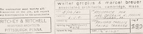
This is a technical architectural drawing, which includes three main views: Elevation, Section, and Plan, of a part of a building structure. 1. **Elevation** - This view is a front perspective that typically shows the vertical dimensions and exterior structure. - It includes multiple vertical lines representing structural elements or the facade of the building. - Specific dimensions are annotated, such as the overall height of 20'-10". 2. **Section** - This view presents a cross-section through the structure, displaying internal components and their relationships at a particular cut line. - You can see detailed notes on elements like beams, framing, and other construction materials. - Dimensions like a 9'-0" span and construction details such as connections and material specifications are noted. 3. **Plan** - This is a horizontal view from above, displaying the arrangement of spaces and structural components. - It shows the layout with labels and measures certain spans and distances along the plan. - It includes exact measurements in feet and inches and notes on additional details or materials used in construction. The drawing is labeled as "RITCHEY & MITCHELL," with the label indicating the involved architects, Walter Gropius and Marcel Breuer, and their associated location of Cambridge, Massachusetts. There is a date of May 17, 1956, and a reference to sheet No. 32, suggesting this is part of a larger set of construction documents.
Anthropic Claude
Created by claude-3-haiku-20240307 on 2024-12-31
The image appears to be an architectural plan or technical drawing. It shows various structural elements, dimensions, and annotations. There are no human faces or identifiable individuals present in the image.
Created by claude-3-opus-20240229 on 2024-12-31
The image shows technical engineering drawings or blueprints. It includes detailed diagrams and schematics with precise measurements and specifications. The drawings appear to be for some kind of construction or fabrication project, likely related to carpentry or woodworking based on the labels that mention "bender trestle" and "mud track". The diagrams are carefully annotated with dimensions and part callouts. Overall, it looks like a set of plans an architect, engineer or skilled craftsperson would create to guide the building and assembly of a wooden structure or apparatus.
Created by claude-3-5-sonnet-20241022 on 2024-12-31
This appears to be an architectural drawing or blueprint showing plans for a trellis structure. The drawing includes three different views: an elevation view, a section view, and a plan view. The details appear to be for a "Revised Trellis" for what's labeled as a "Paved Terrace." The drawing is quite technical, with precise measurements and construction details shown in lines and text. It's drawn in a professional architectural style, with the architect's or firm's title block visible in the bottom right corner. The drawing shows structural elements like support posts and horizontal members that would make up the trellis framework. It's rendered in black lines on a white background, typical of architectural drawings of this type.
Meta Llama
Created by us.meta.llama3-2-11b-instruct-v1:0 on 2025-03-16
The image depicts a technical drawing of a building's elevation and section, showcasing the architectural design and structural elements of the building. **Key Features:** * **Elevation:** The left side of the image displays the elevation of the building, providing a detailed view of its exterior facade. * **Section:** The right side of the image shows the section of the building, offering a cross-sectional view of its interior layout and structural components. * **Plan:** A smaller inset at the bottom left of the image presents the plan of the building, providing a bird's-eye view of its floor plan and layout. * **Text and Labels:** Various text and labels are scattered throughout the image, including measurements, notes, and annotations that provide additional context and information about the building's design and construction. * **Scale and Grid:** A scale and grid are visible in the bottom right corner of the image, allowing for precise measurement and scaling of the building's dimensions. **Overall Impression:** The image appears to be a technical drawing created by an architect or engineer, likely for a construction project or building design. The level of detail and precision suggests that it is a professional-grade drawing, intended for use in the planning and execution of the building's construction.
Created by us.meta.llama3-2-90b-instruct-v1:0 on 2025-03-16
The image depicts a technical drawing of a building's design, showcasing various architectural elements. The drawing is divided into sections, each labeled with specific details and measurements. **Elevation Section:** The top-left section of the drawing displays an elevation view of the building's facade. This section provides a two-dimensional representation of the building's front or side, including features such as windows, doors, and any decorative elements. The elevation view helps architects and builders visualize the building's exterior appearance and ensure that it meets design requirements. **Section View:** Adjacent to the elevation section is a section view, which cuts through the building to reveal its internal structure and layout. This section provides a detailed look at the building's floor plan, including the location of walls, columns, beams, and other structural elements. The section view is essential for understanding the building's overall design and functionality. **Revised Trellis Paved Terrace:** Below the elevation and section views is a revised design for a trellis paved terrace. This section shows a detailed plan for the outdoor space, including the placement of plants, seating areas, and other features. The revised design likely addresses any issues or concerns raised during the initial design phase, ensuring that the final product meets the client's needs and expectations. **Plan View:** At the bottom of the drawing is a plan view, which provides a bird's-eye perspective of the building's layout. This section shows the location of rooms, corridors, and other spaces within the building, as well as the placement of doors, windows, and other architectural features. The plan view is crucial for understanding the building's overall layout and ensuring that it meets functional and aesthetic requirements. **Additional Details:** Throughout the drawing, there are various notes and annotations that provide additional information about the design. These notes may include specifications for materials, dimensions, and other technical details that are essential for the construction process. In summary, the image depicts a technical drawing of a building's design, showcasing various architectural elements and providing detailed information about the building's layout, structure, and functionality. The drawing is divided into sections, each labeled with specific details and measurements, and includes notes and annotations that provide additional context and clarification.
Amazon Nova
Created by amazon.nova-lite-v1:0 on 2025-02-28
The image is a detailed architectural drawing, likely a floor plan or elevation, from an architectural firm. The drawing is on a white background and appears to be a technical document, possibly a blueprint. The drawing includes various sections and elevations, with specific measurements and annotations. The text "Elevation" and "Section" are clearly labeled, indicating that the drawing represents different views of a building or structure. The drawing includes a variety of lines, numbers, and symbols, indicating specific dimensions, materials, and construction details. The drawing also includes the name of the architectural firm, "Ritchey & Mitchell," and the location, "Pittsburgh, Pennsylvania." The drawing is likely a revision of an earlier design, as indicated by the label "Revised Terrace."
Created by amazon.nova-pro-v1:0 on 2025-02-28
The image is a technical drawing of an architectural design. It appears to be a detailed plan for a section of a building, specifically focusing on an exterior wall and a terrace area. The drawing is composed of multiple views and sections, including an elevation, a section, and a plan view. The elevation shows the front view of the wall, indicating the height and materials used. The section view provides a cut-through perspective, revealing the internal structure and layers of the wall. The plan view offers a top-down look at the terrace, showing its layout and dimensions. The drawing includes annotations and measurements, essential for construction and understanding the design intent. The style is typical of architectural blueprints, with precise lines and labels.
Text analysis
Amazon