Machine Generated Data
Tags
Color Analysis
Feature analysis
Amazon
Clarifai

Clarifai
| Envelope | 62.7% | |
Categories
Imagga
created on 2018-03-22
| text visuals | 87.6% | |
| paintings art | 11.8% | |
| food drinks | 0.4% | |
| nature landscape | 0.1% | |
| interior objects | 0.1% | |
Captions
Microsoft
created by unknown on 2018-03-22
| a close up of text on a whiteboard | 81.2% | |
| a close up of a whiteboard | 79% | |
| close up of text on a whiteboard | 78.6% | |
Clarifai
No captions written
Salesforce
Created by general-english-image-caption-blip on 2025-05-11
a photograph of a drawing of a plan for a house
Created by general-english-image-caption-blip-2 on 2025-06-28
a drawing of a house and a plan of the house
OpenAI GPT
Created by gpt-4 on 2025-03-05
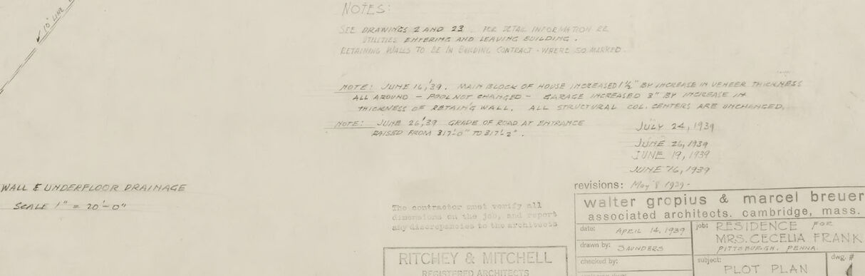
It appears to be an architectural drawing or blueprint featuring a plot plan and detailed sections. These technical drawings are used to plan and construct buildings or landscape features. The main drawing in the center shows a site plan of a building and its immediate surroundings, including contour lines indicating changes in elevation. To the left of the main drawing are smaller detail drawings showing sections of construction elements and plans of specific details, such as a foundation wall.
There are various annotations and dimensions provided throughout, assisting in understanding the design specifications. In the lower right corner, there is text that might reference the project title, date, drawing scale, client, and architect or design firm responsible for the plans.
Such detailed schematics are essential tools for anyone involved in the construction project, from architects and engineers to the construction team on the ground, ensuring that the structure is built according to specifications within a designated property site.
Created by gpt-4o-2024-05-13 on 2025-03-05
The image is a detailed architectural drawing of a site plan, specifically the pilot plan for a residence owned by Mrs. Cecelia Frank. The blueprint includes various elements such as:
- Contour lines indicating the topography of the site, suggesting the elevation changes across the property.
- A layout of the house's footprint with detailed dimensions and notations, depicting the placement and orientation of the building in relation to the surrounding landscape.
- The overall site geometry, including driveways, walkways, and other site-specific elements, is clearly marked.
- Sections A-A’ and B-B’, showing vertical slices through the terrain to demonstrate the land slope and changes in elevation, and a section through a concrete wall and house wall.
- Other architectural elements include a grid system for the site, a north direction indicator, and the revision history noted in the title block in the lower right corner.
- Notations and annotations providing additional information about measurements, materials, and construction details.
- The drawing is completed by the architectural firm Ritchie & Mitchell from Pittsburgh, Pennsylvania, in association with famous architects Walter Gropius and Marcel Breuer, indicating a meticulously planned project with considerable detail.
This drawing serves as a comprehensive guide for the construction and site preparation for the residence.
Anthropic Claude
Created by us.anthropic.claude-3-5-sonnet-20241022-v2:0 on 2025-06-25
This appears to be an architectural drawing or blueprint, specifically a site plan. The drawing is credited to Walter Gropius & Marcel Breuer, Associated Architects. It shows various technical details, sections, and elevations of what appears to be a building project. The drawing includes topographical lines, building footprints, and various architectural notations and measurements. The drawing is done in a professional architectural style typical of mid-20th century documentation, with clean lines and precise technical details. The paper appears aged or yellowed, suggesting this is a historical document.
Created by claude-3-haiku-20240307 on 2024-12-30
This image appears to be an architectural or engineering blueprint. It contains various technical drawings and diagrams, including floor plans, elevations, and details. The image is largely composed of pencil or ink sketches and annotations, suggesting it is a preliminary or working draft of a design. The overall layout and detailed nature of the content indicate this is likely a schematic or technical drawing for some kind of building or structure, though the specific purpose is not explicitly clear from the image alone.
Created by claude-3-opus-20240229 on 2024-12-30
The image shows a detailed architectural blueprint or plan. It includes various sketches and drawings of what appear to be floor plans, sections, and structural details for a building or construction project. There are handwritten notes and dimensions marked on the plans. In the bottom right corner, there is a title block with project information, though the details are not clearly legible in this scan of the drawing. The plans are drawn on off-white paper and have a technical, precise style typical of architectural drafting.
Created by claude-3-5-sonnet-20241022 on 2024-12-30
This is an architectural drawing or blueprint that appears to be for a construction project. The drawing includes several different views and sections of what seems to be a building plan, including floor plans, site layouts, and detailed sections. The drawing is rendered in a technical style with fine lines and measurements typical of architectural drawings.
At the top left, there are some cross-sectional details labeled as "Section A" and other section views. The middle and right portions of the drawing show site contour lines and a more detailed floor plan of the structure. The bottom portion contains what appears to be another site plan view showing the building's placement and orientation.
The drawing has a title block in the lower right corner identifying it as work by Walter Gropius & Marcel Breuer, who were notable architects. The technical nature of the drawing suggests this is a professional architectural document intended for construction or planning purposes.
The scale and level of detail indicate this was likely a working drawing used to communicate design intent to builders or other project stakeholders. The drawing includes various technical notations, dimensions, and construction details that would be necessary for building execution.
Meta Llama
Created by us.meta.llama3-2-11b-instruct-v1:0 on 2025-03-12
The image depicts a vintage architectural blueprint or plan, characterized by its yellowed paper and pencil drawings. The blueprint appears to be a detailed design for a building or structure, featuring various rooms and spaces. It includes measurements, labels, and other annotations that suggest it is a professional or technical document.
Key Features:
- Yellowed Paper: The paper has a warm, aged tone, indicating that it is likely several decades old.
- Pencil Drawings: The blueprint is drawn in pencil, which was a common medium for architectural drawings in the past.
- Detailed Design: The blueprint shows a detailed design for a building or structure, including various rooms and spaces.
- Measurements and Labels: The blueprint includes measurements and labels that suggest it is a professional or technical document.
- Annotations: The blueprint has several annotations, including notes and symbols, that provide additional information about the design.
Overall Impression:
The image suggests that the blueprint is a historic document that has been preserved for its significance or value. It may be a rare or unique example of early 20th-century architecture, and its condition reflects the passage of time.
Created by us.meta.llama3-2-90b-instruct-v1:0 on 2025-03-12
The image presents a detailed architectural drawing of a building's floor plan, showcasing various rooms and spaces. The drawing is rendered in black ink on a white background, with precise measurements and labels indicating the different areas of the building.
Key Features:
- Floor Plan: The central focus of the image is the floor plan, which depicts the layout of the building's interior spaces.
- Rooms and Spaces: The drawing includes several rooms and spaces, each labeled with its intended use or function.
- Measurements: Precise measurements are provided throughout the drawing, allowing for accurate scaling and construction.
- Labels: Labels are used to identify specific features, such as doors, windows, and staircases.
- Background: The background of the image is a plain white surface, providing a clean and neutral backdrop for the architectural drawing.
Overall Impression:
The image provides a clear and detailed representation of the building's floor plan, showcasing the careful planning and attention to detail that has gone into its design. The use of precise measurements and labels ensures that the drawing can be accurately scaled and constructed, making it a valuable resource for architects, builders, and other stakeholders involved in the project.
Amazon Nova
Created by amazon.nova-lite-v1:0 on 2025-01-11
This image is a plot plan of the Harvard University campus in Cambridge, Massachusetts. The plan shows the layout of the campus, including the locations of buildings, roads, and other features. The plan is divided into sections, with each section showing a different part of the campus. The plan includes detailed information about the buildings, such as their dimensions, floor plans, and elevations. The plan also includes notes and annotations that provide additional information about the campus, such as the names of the architects and the dates of construction. The image is a historical document that provides insight into the design and development of the Harvard University campus.
Created by amazon.nova-pro-v1:0 on 2025-01-11
The image is a blueprint of a building, and it is divided into several sections. The blueprint is in black and white, and it is drawn on a white sheet of paper. The blueprint has a lot of details, including the dimensions of the building, the location of the windows, and the location of the doors. The blueprint also has a lot of text, including the names of the architects and the date of the blueprint.
Google Gemini
Created by gemini-2.0-flash on 2025-04-29
The image is an architectural blueprint, primarily in black and white, of a plot plan. The drawing is intricate, with many fine lines and handwritten notes.
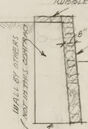
The top portion of the blueprint shows a detailed development of a retaining wall, labeled as "development of retaining way on outer edge of driveway." Below this, there's a plan at point "A," and sections at points "D & C" and "D." These appear to be cross-sectional diagrams illustrating the construction of the retaining wall.
In the center of the blueprint, there's a compass rose indicating the cardinal directions. The main focus of the blueprint seems to be the layout of buildings and structures on the plot. Two buildings are visible, along with contour lines indicating the elevation of the land. Roads and driveways are also shown, connecting the buildings and providing access to the property.
At the bottom right, there's a section with notes and details about the project, including the names "Walter Gropius & Marcel Breuer," who are identified as associated architects from Cambridge, Massachusetts. The project is associated with "Mrs. Cecilia Frank." The blueprint is labeled as "PLOT PLAN" and is identified as sheet number "1." The architecture firm "Ritchey & Mitchell" from Pittsburgh, PA is also credited. There are several dates listed, possibly related to the design or approval process.
In the bottom left, a note mentions a "Wall & Underfloor Drainage" detail. The scale is indicated as "1"=30'-0"."
Created by gemini-2.0-flash-lite on 2025-04-29
Here's a description of the image:
Overall:
This is a blueprint or architectural drawing, likely a plot plan for a building project. It's a technical drawing, likely hand-drawn, showing various elements of the site and the proposed structure. The drawing is on a large sheet of paper.
Key Elements and Layout:
- Top: There are several diagrammatic representations, including horizontal lines, presumably detailing measurements and grading around the proposed area.
- Center: A large portion of the drawing shows a top-down view of the building's outline, incorporated into the surrounding topography.
- Bottom Left: A smaller structure is outlined, indicating a secondary building or area related to the project.
- Sections/Details: There are some cross-sections showing the structural elements of the building
- Callouts: Various annotations, measurements, and notes are written throughout the plan. These detail the measurements and placement of the site.
- Compass Rose: There's a compass rose or diagram showing North, South, East, and West.
- Text and Labels: Numerous handwritten labels, notes, and dimensions are included throughout the drawing. There's also a title block in the bottom right corner.
Inferences:
- The drawing style suggests a vintage origin.
- The level of detail indicates a detailed plan.
- It's likely a plan for a residential or a small commercial building.
Overall, the image gives the impression of a carefully planned building project.
Mistral Pixtral
Created by us.mistral.pixtral-large-2502-v1:0 on 2025-05-27
The image is an architectural drawing or blueprint. Here are the key elements visible in the image:
Title Block:
- Located at the bottom right corner.
- Contains information such as the title of the project, the names of the architects (Walter Gropius & Marcel Breuer), the location (Pittsburgh, Pennsylvania), and the date (July 1944).
- Includes a scale and a reference number (1).
Main Drawing:
- The central part of the drawing shows a detailed floor plan of a building.
- The plan includes various rooms and spaces, with dimensions and labels indicating the purpose of each area.
- There are several annotations and notes providing additional details about the design and construction.
Additional Drawings:
- To the left of the main drawing, there are smaller, detailed drawings.
- These likely represent specific sections or elements of the building, such as elevations, cross-sections, or detailed views of particular features.
Annotations and Notes:
- Throughout the drawing, there are handwritten notes and annotations.
- These notes provide additional information about the design, materials, dimensions, and other relevant details.
Scale and Measurements:
- The drawing includes a scale, which is essential for understanding the actual sizes of the elements depicted.
- Measurements are provided for various parts of the building, ensuring accuracy in construction.
Overall, the image is a detailed architectural plan that provides a comprehensive overview of a building's design, including floor plans, sections, and specific details necessary for construction.
Qwen
No captions written
Text analysis
Amazon