Machine Generated Data
Tags
Color Analysis
Feature analysis
Amazon
Clarifai

AWS Rekognition
| Rug | 67.7% | |

Categories
Imagga
created on 2018-03-22
| text visuals | 99.9% | |
Captions
Microsoft
created by unknown on 2018-03-22
| a close up of text on a white surface | 59.6% | |
| a close up of a computer screen with text | 44.1% | |
| a screenshot of a computer | 44% | |
Clarifai
No captions written
Salesforce
Created by general-english-image-caption-blip on 2025-05-11
a photograph of a plan of a plan of a house with a plan of a house
Created by general-english-image-caption-blip-2 on 2025-06-28
a drawing of a building plan with several different floor plans
OpenAI GPT
Created by gpt-4 on 2025-03-08
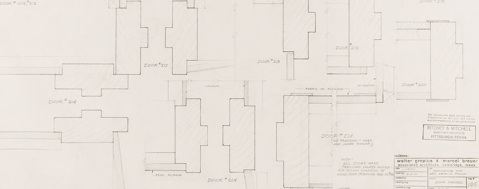
This image is a technical drawing or architectural blueprint showing a series of door details. There are multiple panels each showing different door designs with specified dimensions and annotations indicating the materials or design elements such as "GLASS," "CORE TILE," and "3PLY WOOD." Each door seems to come with annotations for different parts of the door hardware or framing, detailed from various angles or cross-sections.
In the bottom right corner, there appears to be information about the project or the architects involved with the design—names such as "Ritchey & Mitchell Pittsburgh, Penna" and "Walter Gropius & Marcel Breuer, Associated Architects, Cambridge, Mass."
The technical nature of these drawings suggests that they are likely meant for construction or manufacturing purposes, enabling builders or craftsmen to understand how each door should be constructed and what materials are to be used. The notation "DOOR," followed by numbers (like "DOOR #215," "DOOR #216," etc.), indicates that there are multiple door designs possibly for different areas or rooms within a structure.
The presence of the architects Walter Gropius, a renowned modern architect and founder of the Bauhaus School, and Marcel Breuer, also associated with Bauhaus and known for his furniture designs, indicates that this could be a historical document from a significant modernist project.
Created by gpt-4o-2024-05-13 on 2025-03-08
The image is a technical drawing displaying detailed schematics of various door and frame profiles. It includes multiple sections of doors, each labeled with an identifier such as "DOOR #206/212" or "DOOR #214". The profiles illustrate different standardized cutouts and the materials used in construction, such as glass, cork tile, and plywood.
Significant annotations and markings include specifications about the dimensions, materials, and assembly instructions. There's a title block on the lower right corner providing details about the architects (Ritchey & Mitchell) and their associates (Walter Gropius & Marcel Breuer), their location (Pittsburgh, Penna), and the project details such as revision counts and date.
The drawing appears to be carefully drafted using precise line work, indicative of architectural or engineering plans likely used for construction or manufacturing purposes. There are indications of measurements and notes that ensure accurate implementation of these door designs.
Anthropic Claude
Created by us.anthropic.claude-3-5-sonnet-20241022-v2:0 on 2025-06-25
This appears to be an architectural drawing or blueprint showing door frame details. The drawing contains multiple technical illustrations of door profiles and their framing specifications. The document appears to be from an architectural firm "Walter Gropius & Marcel Breuer" from Cambridge, Massachusetts. The project seems to be for "Richey & Mitchell" in Pittsburgh, Pennsylvania. The drawing includes various door numbers (like "Door #214", "Door #213", etc.) and shows detailed cross-sections and elevations of different door configurations. The drawing is primarily in black and white with clean, technical line work typical of architectural drawings from this era.
Created by claude-3-haiku-20240307 on 2024-12-30
This image appears to be an architectural drawing or blueprint. It contains various rectangular shapes and lines that resemble floor plans or schematic diagrams for a building or structure. The drawings are labeled with dimensions and annotations, indicating that this is a technical document used for construction or design purposes. There are no human figures or faces visible in the image.
Created by claude-3-5-sonnet-20241022 on 2024-12-30
This is an architectural drawing or technical blueprint showing various door frame profiles and specifications. The image appears to be a detailed construction document that includes multiple door cross-sections or elevations labeled with numbers (like "Door #214," "Door #215," etc.). The drawing is done in a professional drafting style with clean lines and precise measurements. It's from an architectural firm named "Walter Gropius & Marcel Breuer" based in Cambridge, Massachusetts, and appears to be for a project for Richey & Mitchell in Pittsburgh, Pennsylvania. The drawing focuses on door frame details and their various configurations, showing different cuts and dimensions for what appears to be a larger construction project.
Meta Llama
Created by us.meta.llama3-2-11b-instruct-v1:0 on 2025-03-15
The image is a technical drawing of a building's floor plan, specifically focusing on the layout of doors and doorways. The drawing is presented in a monochromatic style, with black lines on a white background.
Key Features:
- Door Layout: The drawing showcases the arrangement of doors and doorways throughout the building. Each door is labeled with a unique identifier, such as "DOOR * 208 * 212" or "DOOR * 204". These labels are accompanied by additional information, including the door's width and any notable features like windows or transoms.
- Door Types: The drawing distinguishes between different types of doors, including:
- Standard Doors: These are represented by simple rectangles with a door handle and hinges.
- Sliding Doors: These are depicted as sliding panels with a track and rollers.
- Folding Doors: These are shown as folding panels that can be opened and closed.
- Door Openings: The drawing highlights the door openings, which are represented by rectangles with a door frame and a door jamb. Some door openings have additional features, such as a transom window above the door or a sidelight on either side.
- Dimensions: The drawing includes measurements for each door and doorway, providing precise information about their size and location within the building.
- Labels and Annotations: Throughout the drawing, there are various labels and annotations that provide additional context and information about the doors and doorways. These include notes about the door's function, the type of door, and any special requirements or restrictions.
Overall Impression:
The image presents a detailed and technical representation of a building's floor plan, focusing on the layout of doors and doorways. The use of labels, annotations, and measurements creates a clear and concise visual representation of the building's design. The monochromatic color scheme and simple line work contribute to the overall sense of clarity and precision, making it easy to navigate and understand the drawing.
Created by us.meta.llama3-2-90b-instruct-v1:0 on 2025-03-15
The image presents a detailed architectural drawing of a floor plan, showcasing the layout and design of a building's interior. The drawing is rendered in black ink on white paper, with precise lines and measurements that provide a clear understanding of the space.
Key Features:
- Floor Plan: The drawing depicts a floor plan with various rooms, corridors, and doors, each labeled with a unique identifier (e.g., "DOOR #208" or "ROOM 214").
- Room Layouts: The rooms are rectangular in shape, with some featuring internal partitions or walls that divide the space into smaller areas.
- Corridors and Doors: The corridors are narrow and straight, connecting the rooms and providing access to different parts of the building. Doors are strategically placed to facilitate movement between rooms and corridors.
- Measurements and Labels: The drawing includes measurements and labels that indicate the size and purpose of each room, as well as the location of doors, windows, and other features.
- Architectural Details: The drawing also includes architectural details such as staircases, elevators, and other structural elements that support the building's design.
Overall Impression:
The image provides a comprehensive view of the building's interior, highlighting the careful planning and attention to detail that has gone into its design. The use of precise lines, measurements, and labels creates a sense of order and functionality, suggesting that the building is intended for a specific purpose, such as an office or residential complex.
Amazon Nova
Created by amazon.nova-pro-v1:0 on 2025-01-12
The image is a blueprint of a building, which is a detailed architectural plan. The blueprint is divided into several sections, each labeled with specific measurements and dimensions. The blueprint is divided into two main sections, with the left section labeled "DOOR 205" and the right section labeled "DOOR 212." Each section is further divided into smaller sections, with measurements and dimensions provided for each section. The blueprint also includes notes and instructions for the construction of the building, such as "PARK IN FORWARD" and "HEAD OVER TRANSOM SEE NOTE." The blueprint is a detailed plan for the construction of a building, with specific measurements and instructions provided for each section.
Created by amazon.nova-lite-v1:0 on 2025-01-12
The image is a detailed architectural floor plan, possibly from a residential or commercial building. The plan is drawn in pencil on a large piece of paper and includes various sections marked with dimensions and notes. The layout is divided into several sections, each containing multiple rooms or spaces. Doors are marked with their dimensions, such as "DOOR 206" and "DOOR 215," and are shown in various positions and sizes. The plan also includes notes and measurements for different areas, such as "PARK 10 PUTNED" and "PARK 15 EN PUTNED." The image has a vintage look, suggesting it is an older architectural drawing.
Google Gemini
Created by gemini-2.0-flash on 2025-05-12
Here's a description of the image:
Overall Impression:
The image is a technical architectural drawing, likely a detail sheet, showing cross-sectional views of various door frames. It appears to be a scanned document, possibly hand-drawn or a print of a drawing.
Key Elements:
- Multiple Door Frame Sections: There are several distinct cross-sectional diagrams representing different door frame configurations. Each is labeled with a number, such as "Door # 205/211" or "Door #214".
- Construction Details: The drawings show the layering and materials used in the door frames. Labels indicate "glass," "cork tile," "5/8" studs," "fabric on plaster," and "plywood".
- Descriptive Text: There is handwritten and printed text giving specifications and notes about the door frames. For example, one note mentions that "All doors have transom unless noted".
- Architectural Firm Information: In the lower right corner, there is a stamp or printed information about the architectural firm: "Ritchey & Mitchell, Registered Architects, Pittsburgh, Penna."
- Project Information: The drawing includes information about the project and the architects: "Walter Gropius & Marcel Breuer, associated architects, Cambridge, Mass". There's also a title: "Door Frames", and a sheet number: "195".
Style and Tone:
The image has a technical and formal tone, consistent with architectural documentation. The lines are precise and the labels are clear and concise.
Overall, the image is a historical record of the construction details for door frames in a building designed by Walter Gropius and Marcel Breuer, two prominent architects of the 20th century.
Created by gemini-2.0-flash-lite on 2025-05-12
This is a technical drawing, likely an architectural plan or detail drawing. It appears to be a collection of various door frame cross-sections, with labels and annotations.
Here's a breakdown:
- Perspective: The drawing presents cross-sections, showing how the door frames fit into the wall structure.
- Details: The drawing includes notes on materials (glass, cork tile, fabric on plywood, etc.) and specific measurements (like "5 5/8" studs").
- Labels: Each door frame has a number (e.g., Door *208, Door *216). This suggests that the drawing is part of a larger set of plans, with each door type having a unique identifier.
- Title Block: A title block in the lower-right corner indicates that the drawing is for "DOOR FRAMES" and was created by "Walter Gropius & Marcel Breuer, associated architects, Cambridge, Mass." The firm "RITCHEY & MITCHELL" is also present.
- Annotations: The drawing has notes regarding transoms.
In summary, this drawing provides technical information about how to construct and install different types of door frames within a building, and is likely from an architectural plan set.
Mistral Pixtral
Created by us.mistral.pixtral-large-2502-v1:0 on 2025-05-30
The image is a detailed architectural drawing, specifically a floor plan, likely of a building or a specific floor within a building. Here are the key elements and features observed in the drawing:
Door and Room Labels:
- The plan includes multiple rooms, each labeled with a door number (e.g., DOOR 208, DOOR 209, DOOR 210, etc.).
- Some rooms are labeled with specific functions, such as "GYM STOR," "GIRLS," "BOYS," "GAMES," "LIBRARY," and "CRAFTS."
Room Layout:
- The layout shows various rooms of different sizes and shapes.
- There are indications of partitions and walls, with some rooms having specific features like "PARTITION" or "PARTITION IN PLYWOOD."
Measurements and Dimensions:
- The drawing includes precise measurements and dimensions for various elements, such as door sizes and wall lengths.
- There are notes on specific dimensions, such as "HEAD OVER TRANSOM 600" and "DOOR 208 2/0 X 7/0."
Architectural Firms:
- The drawing credits two architectural firms: "MITCHELL & MITCHELL" from Pittsburgh, Pennsylvania, and "WALTER GROPIUS & MARCEL BREUER ASSOCIATED ARCHITECTS" from Cambridge, Massachusetts.
Drawing Details:
- The drawing is dated "1/27/47," indicating it was created on January 27, 1947.
- There is a note stating that the construction must conform to all requirements of the building code.
- The drawing is marked as "Sheet 5 of 6."
Materials and Finishes:
- Some rooms have specific notes on materials and finishes, such as "DOORS PAINTED" and "PARTITION IN PLYWOOD."
This detailed floor plan provides a comprehensive layout of the rooms, their dimensions, and specific architectural details necessary for construction or renovation.
Qwen
Created by Qwen/Qwen2.5-VL-7B-Instruct on 2025-07-20
The image appears to be a detailed architectural drawing, specifically a set of door frame layouts. Each layout is labeled with a unique identifier, such as "DOOR * 205," "DOOR * 210-215," and so on, indicating different door frame designs or specifications. The drawings are technical and precise, with lines and shading used to represent the various materials and dimensions of the door frames. Some of the labels also include additional notes, such as "DOOR * 204 (NO TRANSOM - HEAD AND JAMB SIMILAR)," which specifies a particular feature of that particular door frame. The bottom right corner of the image includes a company name, "RITCHIE & MITCHELL, ARCHITECTS, PITTSBURGH, PENNA," and a reference to "DOOR FRAMES" and the number "195." This suggests that the drawings are part of a larger set or project related to door frames and are possibly part of a historical or vintage architectural document.
Created by Qwen/Qwen2.5-VL-72B-Instruct on 2025-07-20
This is a technical architectural drawing or blueprint, showcasing a series of door frames and their cross-sections, likely designed for a building project. The image includes several vertical sections of doors, each labeled with specific door numbers and dimensions. Here are the key features of the drawing:
Door Frames and Sections:
- The drawing displays various door frames, each with detailed cross-sections.
- The sections show the construction details of the door frames, including materials and assembly.
- The door frames are labeled with numbers such as "DOOR 205," "DOOR 210," "DOOR 215," etc., indicating different types or sizes of doors.
Materials and Construction:
- Some sections include annotations like "GLASS," "CORK TILE," and "5" STUDS," suggesting the materials used in the door construction.
- The cross-sections show the layers of materials, such as glass panels, cork tiles, and wooden studs, indicating a detailed design for both aesthetics and functionality.
Annotations and Notes:
- There are various annotations and notes on the drawing, providing additional information about the design and construction.
- The bottom right corner includes a note stating "ALL DOORS HAVE TRANSOMS UNLESS NOTED," indicating a standard design feature for the doors.
Architectural Firm and Project Information:
- The drawing is attributed to "Walter Gropius & Marcel Breuer" and "Ritchey & Mitchell," suggesting that these architects and engineers were involved in the project.
- The location "Pittsburgh, Penna" (Pennsylvania) is mentioned, indicating the project's location.
Drawing Details:
- The drawing is detailed and precise, with clear lines and shading to differentiate between different materials and components.
- The scale and orientation of the drawing are consistent, making it easy to understand the dimensions and proportions of the door frames.
Overall, this blueprint is a comprehensive guide for constructing various door frames, providing detailed information about materials, dimensions, and assembly for a building project in Pittsburgh, Pennsylvania.
Text analysis
Amazon