Machine Generated Data
Tags
Color Analysis
Feature analysis
Amazon
| Rug | 71% | |
Categories
Imagga
| text visuals | 99.3% | |
| paintings art | 0.5% | |
| interior objects | 0.1% | |
Captions
Microsoft
created on 2018-03-22
| a close up of text on a white background | 74.3% | |
| a close up of text on a white surface | 71.2% | |
| a close up of text on a black background | 67.3% | |
OpenAI GPT
Created by gpt-4 on 2025-03-07
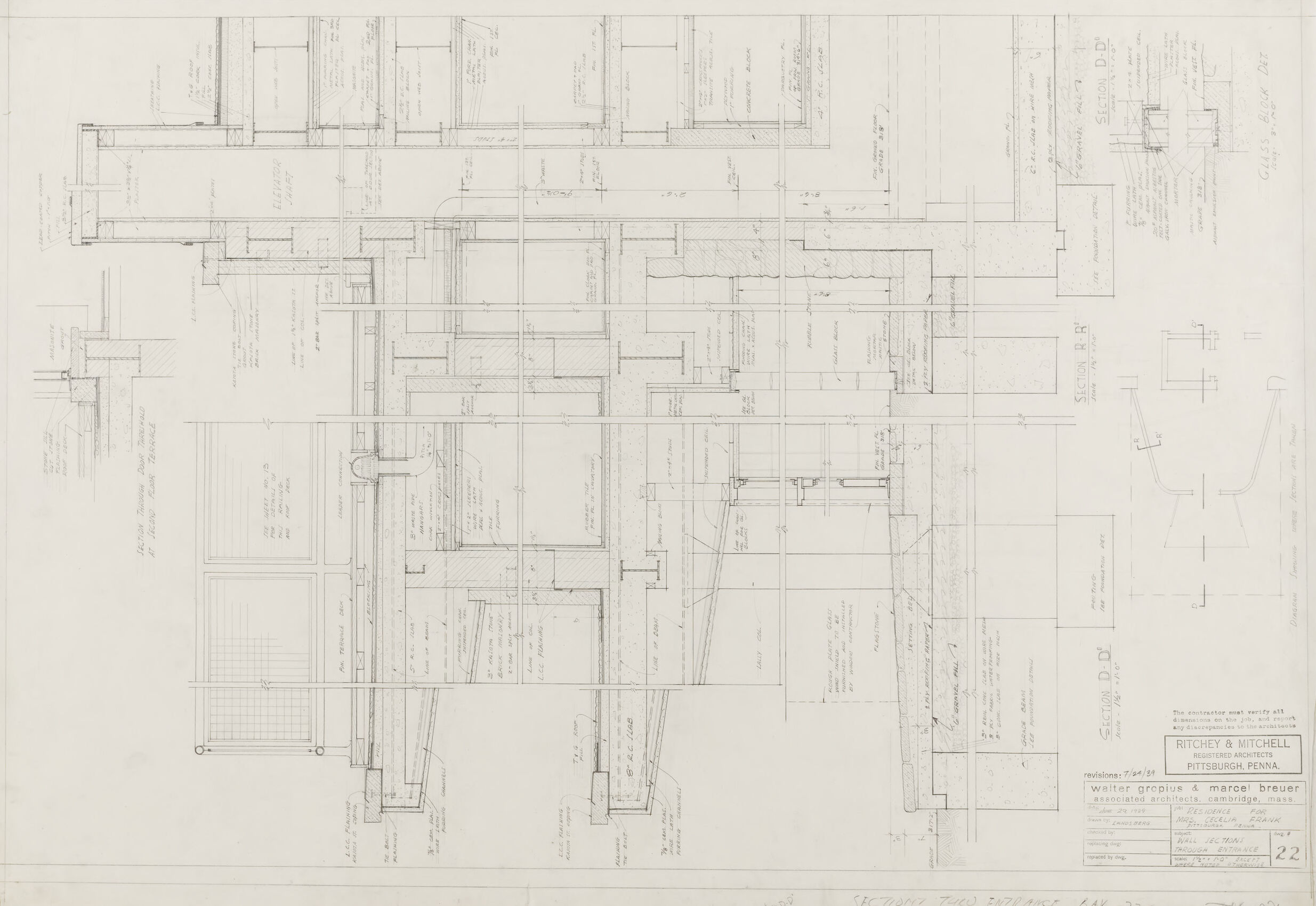
This image displays an architectural blueprint. The blueprint shows an intricate layout of a building or structure from a top-down perspective, detailing walls, rooms, and various other architectural features. Annotations and measurements are provided throughout the plan, indicating dimensions, construction notes, and materials, which are essential for guiding the construction process. The plan is drawn to scale and includes section lines, which likely correspond to detailed cross-section drawings elsewhere in the set of blueprints. There is visible text on the blueprint, such as "Section thru Entrance Lobby" along with the names of the architecture firms involved in the design. There is also a stamp or seal from the architects, and possibly revisions or approval dates. The paper itself seems aged, with creases and possible wear signs at the edge, suggesting that the blueprint is a physical document that might have been used during actual building construction or planning.
Created by gpt-4o-2024-05-13 on 2025-03-07
The image depicts an architectural drawing, which appears to be a detailed section of a building. The drawing is meticulously rendered with fine lines and precise annotations that suggest various structural elements and construction details. Key features within this architectural section include labeled measurements, technical instructions, and cross-references to other parts of the design. This blueprint includes the stamp of "Ritchey & Mitchell Registered Architects, Pittsburgh, Penna," as well as the logo and name of "Walter Gropius & Marcel Breuer, Associated Architects, Cambridge, Mass." A specific note mentions "Section Thru Entrance Bay–22," indicating the detailed section view through an entrance bay area. Materials, dimensions, and construction methods are annotated, providing instructions for builders and contractors. The drawing includes labels for individual sections named "SECTION D-D" and "SECTION R-R," among others, each of which likely corresponds to specific views or parts of the structure. The craftsmanship and specificity indicate that this is a professional, technical document used in the construction industry.
Anthropic Claude
Created by claude-3-haiku-20240307 on 2024-12-29
This image appears to be an engineering diagram or technical drawing. It shows a complex arrangement of geometric shapes, lines, and annotations, indicating a detailed schematic or blueprint of some kind of mechanical or architectural structure. The drawing is filled with intricate details, measurements, and technical specifications, suggesting this is a highly technical and detailed engineering plan or design. Without being able to identify any specific individuals, the image seems to depict a detailed technical illustration or construction plan.
Created by claude-3-opus-20240229 on 2024-12-29
The image shows an architectural blueprint or floor plan drawing. It depicts the layout and measurements for what appears to be a residential or commercial building. The plan includes various rooms, walls, doors, windows and other structural elements. Handwritten notes and dimensions are marked throughout the blueprint. The image is rendered in black and white with a grid pattern in the background, giving it a technical drafting style typical of architectural plans.
Created by claude-3-5-sonnet-20241022 on 2024-12-29
This is an architectural drawing showing detailed section views and technical specifications. It appears to be a building section drawing created by Ritchey & Mitchell from Pittsburgh, Pennsylvania. The drawing contains various cross-sectional details of what seems to be building components, with precise measurements and annotations. The drawing is primarily in black and white, executed in a technical drafting style typical of architectural documents. The layout includes multiple detailed sections showing different structural and architectural elements, with dimensions and construction notes. At the bottom right of the drawing, there's a title block with project information and drawing number. The drawing style suggests this is likely from a professional architectural or engineering project documentation set.
Meta Llama
Created by us.meta.llama3-2-11b-instruct-v1:0 on 2025-03-14
The image presents a detailed architectural blueprint for a building, showcasing the intricate design and layout of the structure. The blueprint is rendered in black and white, with various lines, symbols, and notations that provide a wealth of information about the building's design and construction. **Key Features:** * **Scale:** The blueprint is drawn to scale, allowing architects and builders to accurately measure and construct the building. * **Floor Plan:** The blueprint features a floor plan that outlines the layout of the building, including the location of rooms, corridors, and other features. * **Elevations:** The blueprint also includes elevations, which provide a detailed view of the building's exterior and interior walls, windows, and doors. * **Sections:** The blueprint includes sections, which are vertical cuts through the building that provide a detailed view of the structure's internal components, such as the foundation, walls, and roof. * **Notations:** Throughout the blueprint, there are various notations and symbols that provide additional information about the building's design and construction. These notations may include details about materials, dimensions, and other specifications. **Overall Impression:** The blueprint provides a comprehensive and detailed view of the building's design and construction. The level of detail and precision suggests that the blueprint was created by a skilled architect or engineer who took great care in ensuring that every aspect of the building's design was accurately represented. The blueprint is likely to be an essential tool for builders, contractors, and other stakeholders involved in the construction process.
Created by us.meta.llama3-2-90b-instruct-v1:0 on 2025-03-14
The image presents a detailed architectural blueprint, likely created for a building or structure. The blueprint is rendered in black ink on a white background, with various lines, symbols, and notations that provide information about the design and construction of the building. **Key Features:** * **Title Block:** A title block is located in the bottom-right corner of the blueprint, containing essential information such as the project name, architect's name, and date. * **Floor Plan:** The majority of the blueprint depicts a floor plan, showcasing the layout of rooms, corridors, and other features within the building. * **Elevations:** Several elevations are included, providing a visual representation of the building's exterior and interior walls. * **Sections:** A few sections are also present, offering a detailed view of specific areas of the building, such as staircases or doorways. * **Notations:** Throughout the blueprint, various notations and symbols are used to convey important details, such as room dimensions, material specifications, and construction methods. * **Scale:** A scale is provided in the bottom-left corner, allowing users to accurately measure distances and sizes within the blueprint. **Overall Impression:** The blueprint appears to be a comprehensive and detailed design for a building, likely created by an architect or engineer. The inclusion of various elevations, sections, and notations suggests that the blueprint is intended for use in the construction process, providing a clear and accurate guide for builders and contractors.
Amazon Nova
Created by amazon.nova-lite-v1:0 on 2025-01-10
The image is a technical architectural drawing, likely a floor plan or a section view of a building. The drawing is detailed and shows various structural elements and annotations. The layout includes several labeled sections, such as "SECTION D-D," "SECTION R-R," and "SECTION B-B," indicating different cross-sectional views of the building. The drawing is divided into multiple grids and includes dimensions, measurements, and notes on the structural components. The drawing appears to be a professional architectural plan, possibly for a residential or commercial building. The drawing is in black and white, typical of architectural plans, and includes text that reads "RITCHEY & MITCHELL," "REGENERATED ARCHITECTS PITTSBURGH PENNA," and "WALTER GROPIUS & MARCEL BREUR," indicating the architects and their location.
Created by amazon.nova-pro-v1:0 on 2025-01-10
The image shows a detailed architectural blueprint of a building. It is a large piece of paper with a grid pattern, and the blueprint is drawn on it. The blueprint includes various sections of the building, such as the floor plan, elevations, and sections. The blueprint also includes dimensions, notes, and other details. The blueprint is labeled with the names of the architects and the date of the drawing.
Text analysis
Amazon