Machine Generated Data
Tags
Color Analysis
Categories
Imagga
| text visuals | 99.7% | |
| paintings art | 0.3% | |
Captions
Microsoft
created on 2018-03-22
| a close up of text on a white background | 78.2% | |
| a close up of text on a white surface | 75.8% | |
| a close up of text on a black background | 72.7% | |
OpenAI GPT
Created by gpt-4 on 2025-03-08
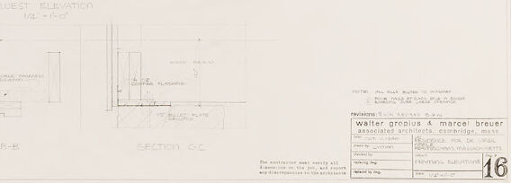
This image is a technical drawing, specifically an architectural blueprint or plan. It shows a series of detailed architectural drawings including elevations and sections of a building. Drawings like these are used in the construction and design of buildings and contain precise measurements and annotations to guide the building process.
The main drawing in the center appears to be a west elevation view, indicating it is a depiction of the building as seen from the west side. Surrounding the main elevation there are multiple section drawings labeled "SECTION A-A," "SECTION B-B," and "SECTION C-C" showing the interior cut-throughs of the structure at different points.
There is text and numerical data on the blueprint that provide specifications such as dimensions, materials, and other construction details. At the bottom right corner, there’s a title block containing information such as the project title, architects' names, associated architectural firm, scale, and other identifiers like sheet number.
Please note that some details might not be clear due to the resolution of the image and the fine print of the text.
Created by gpt-4o-2024-05-13 on 2025-03-08
The image is an architectural drawing, specifically a detailed plan showing the West Elevation and several section drawings labeled A-A, B-B, and C-C. The drawing includes various measurements and structural details of a building. It appears to come from the office of Walter Gropius & Marcel Breuer, prominent architects, as indicated by the text in the lower right corner. The drawing includes labeled dimensions and annotations relating to the building's floors and key structural elements such as floor and ceiling levels, roof slopes, and other architectural features. The overall precision and layout suggest that this plan is part of a professional architectural blueprint used for building or reference purposes.
Anthropic Claude
Created by claude-3-haiku-20240307 on 2024-12-30
The image appears to be a detailed architectural drawing or technical plan. It shows various elevations, sections, and dimensions of what seems to be a building or structure. The drawing contains technical annotations, measurements, and other architectural details, but does not depict any human figures or faces. Without being able to identify any individuals, the image appears to be a professional technical illustration or engineering design.
Created by claude-3-opus-20240229 on 2024-12-30
The image shows architectural drawings or blueprints for what appears to be a water storage and treatment plant. The drawings depict various sections, elevations and floor plans with technical labels and dimensions. At the bottom, there is a title block that says "WATER STORAGE & TREATMENT PLANT" along with some additional notes about revisions and drawing numbers. The drawings are done in thin black lines on a white background, giving it a clean and technical appearance typical of architectural plans.
Created by claude-3-5-sonnet-20241022 on 2024-12-30
This is an architectural drawing showing various sections and elevations of a building design. The main part of the drawing shows a west elevation view with multiple floor levels clearly marked. Below the elevation, there are three cross-sectional views labeled as Section A-A, Section B-B, and Section C-C, which provide additional detail about the building's internal structure. The drawing appears to be a professional architectural blueprint with precise measurements and technical details. In the bottom right corner, there appears to be a title block with project information, though the text is not clearly legible in this image. The drawing is rendered in a traditional architectural style using thin lines on what appears to be white paper or vellum.
Meta Llama
Created by us.meta.llama3-2-11b-instruct-v1:0 on 2025-03-15
The image is a technical drawing of a building's floor plan, featuring a detailed layout of rooms and spaces. The drawing is rendered in black ink on white paper, with various symbols and notations used to convey specific information about the building's design and construction.
Key Features:
- Floor Plan: The drawing depicts a two-story building with multiple rooms and corridors, including a lobby, offices, and meeting rooms.
- Dimensions: The drawing includes measurements and scales to provide a clear understanding of the building's size and layout.
- Symbols and Notations: Various symbols and notations are used throughout the drawing to indicate different features, such as doors, windows, and electrical outlets.
- Text: The drawing includes text labels and annotations to provide additional information about the building's design and construction.
Overall Impression:
The image presents a detailed and technical representation of a building's floor plan, showcasing the careful consideration and planning that went into its design and construction. The use of symbols and notations adds an extra layer of complexity and precision to the drawing, highlighting the attention to detail required for a project of this scope.
Created by us.meta.llama3-2-90b-instruct-v1:0 on 2025-03-15
The image presents a technical drawing of a building's floor plan, likely created by an architect or designer. The drawing is rendered in black ink on white paper and features various lines, symbols, and notations that provide detailed information about the building's layout and design.
Key Features:
- Floor Plan: The main focus of the drawing is the floor plan, which shows the layout of the building's rooms, corridors, and other spaces.
- Elevations: The drawing also includes elevations, which are side views of the building that show its height and exterior features.
- Sections: In addition to the floor plan and elevations, the drawing includes sections, which are cross-sectional views of the building that show its internal structure and layout.
- Notations: Throughout the drawing, there are various notations and symbols that provide additional information about the building's design and construction. These may include notes about materials, dimensions, and other relevant details.
- Scale: The drawing is likely drawn to scale, which means that the proportions of the building's features are accurately represented.
- Legend: A legend or key may be included in the drawing to explain the meaning of the various symbols and notations used.
Purpose:
The purpose of this technical drawing is to provide a detailed and accurate representation of the building's design and layout. It is likely used by architects, engineers, contractors, and other stakeholders involved in the construction process to ensure that the building is built according to plan.
Conclusion:
In conclusion, the image presents a technical drawing of a building's floor plan, elevations, and sections, along with various notations and symbols that provide detailed information about the building's design and construction. The drawing is likely used by professionals in the construction industry to ensure that the building is built accurately and safely.
Amazon Nova
Created by amazon.nova-lite-v1:0 on 2025-01-13
This image is a blueprint for a building, showing the floor plans and elevations. The blueprint includes detailed measurements and annotations, indicating the dimensions and layout of the building's various sections. The floor plans show the layout of the rooms and spaces on each floor, while the elevations show the building's exterior and interior walls, including windows, doors, and other features. The blueprint also includes notes and annotations, such as the names of the architects and contractors involved in the project, as well as the date and revision number of the blueprint.
Created by amazon.nova-pro-v1:0 on 2025-01-13
The image is a drawing of the floor plan of a building. The drawing is divided into three sections, labeled A-A, B-B, and C-C. The drawing is labeled "WEST ELEVATION" and "1/4" = 1'-0". The drawing shows the layout of the building, including the location of walls, doors, and windows. The drawing also includes dimensions and notes. The drawing is in black and white.
Text analysis
Amazon