Machine Generated Data
Tags
Color Analysis
Categories
Imagga
| text visuals | 99.9% | |
| paintings art | 0.1% | |
Captions
Microsoft
created by unknown on 2018-03-22
| a close up of text on a white background | 76.8% | |
| a close up of text on a black background | 72.1% | |
| a close up of text on a white surface | 72% | |
Clarifai
created by general-english-image-caption-blip on 2025-05-14
| a photograph of a drawing of a plan for a house | -100% | |
OpenAI GPT
Created by gpt-4 on 2025-03-09
This image displays a set of architectural drawings or blueprints. Such drawings typically include detailed plans and elevations required for the construction of a building or structure. Here's what the image shows:
- There are multiple views on the page, indicating different sections and elevations of a structure.
- Each view is labeled with technical descriptions, measurements, and notes that provide specific information on the dimensions and construction details.
- The drawings feature straight lines, hatchings, and annotations indicating various structural elements and materials.
- There's text along the bottom border, possibly including names, titles, dates, or revision notes related to the project or the architects involved.
- The paper appears to be large-format, which is standard for architectural plans to ensure clarity and detail can be accurately conveyed.
- The drawing style suggests that these plans could be for a modern or contemporary structure, given the clean lines and precise detailing.
These types of drawings are essential in the design and construction process, allowing architects to communicate their designs to clients, contractors, and building officials.
Created by gpt-4o-2024-05-13 on 2025-03-09
The image depicts a detailed architectural drawing. The drawing is labeled with various sections and elevations of a building, showcasing a structural cross-section of the layout. Given the labels visible, one part of the drawing identified is the 'South Elevation' of the building at a scale of 1/4” = 1’0”.
Additionally, there are subsections noted as Section A-A, Section B-B, and Section C-C. These sections provide more intricate details about the specific structural elements within the building, such as trusses, flooring, and foundation elements.
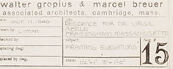
The lower right corner of the blueprint contains title block information, revealing that the architects are Walter Gropius and Marcel Breuer, associated with Architects Collaborative in Cambridge, Massachusetts. The drawing is part of a project, and it seems to be sheet number 15 in a series, indicating a set of technical drawings for construction or design purposes.
Anthropic Claude
Created by claude-3-haiku-20240307 on 2024-12-31
This image appears to be an architectural blueprint or engineering diagram. It contains detailed technical drawings and schematics, including various measurements, notes, and annotations. The layout and presentation suggest this is likely a construction or design plan for a building or structure. The image does not contain any human faces, so I will simply describe the contents without identifying any individuals.
Created by claude-3-opus-20240229 on 2024-12-31
The image shows architectural plans or blueprints for what appears to be a building or structure. It contains detailed technical drawings with measurements, annotations, and labels indicating different sections and elements of the design. The plans depict floor layouts, elevations, and cross-sections drawn to scale. The text and numbering provide specifications and dimensions for the various structural components. Overall, it is a professional architectural schematic illustrating the precise design and layout of a constructed project.
Created by claude-3-5-sonnet-20241022 on 2024-12-31
This appears to be an architectural drawing or blueprint showing various sectional elevations and details. The drawing includes multiple sections labeled "SECTION A-A," "SECTION B-B," and "SECTION C-C," along with what appears to be a "SOUTH ELEVATION" view. The drawing is quite detailed with various floor levels indicated and dimensional markings throughout. The drawing is rendered in a technical style typical of architectural documents, with thin lines and precise measurements. At the bottom right corner, there appears to be a title block with what looks like project information and a page number "15". The drawing seems to be focused on showing the vertical relationships between different levels of a structure, including what appear to be various floor plates and spatial divisions.
Meta Llama
Created by us.meta.llama3-2-11b-instruct-v1:0 on 2025-03-16
The image presents a technical drawing of a building's floor plan, showcasing its architectural design and layout. The drawing is rendered in black ink on white paper, with various sections labeled and annotated with notes.
- Floor Plan:
- The floor plan is divided into several sections, each representing a different level or area of the building.
- The sections are labeled with letters and numbers, indicating their location and purpose.
- The drawing includes various symbols and notations, such as arrows and lines, to illustrate the relationships between different elements of the building.
- Annotations:
- The drawing features numerous annotations, including text and symbols, that provide additional information about the building's design and construction.
- These annotations may include details about materials, dimensions, and other technical specifications.
- Some annotations appear to be handwritten, while others are printed or typed.
- Symbols and Notations:
- The drawing employs a range of symbols and notations to convey complex information about the building's design and construction.
- These symbols and notations may include arrows, lines, and other geometric shapes to illustrate relationships between different elements of the building.
- Some symbols and notations appear to be standardized, while others may be unique to the specific project or architect.
- Overall Impression:
- The drawing conveys a sense of precision and attention to detail, suggesting that it was created by a skilled architect or engineer.
- The use of various symbols and notations adds complexity to the drawing, but also provides a wealth of information about the building's design and construction.
- Overall, the drawing appears to be a detailed and informative representation of the building's floor plan, providing valuable insights into its architecture and design.
In summary, the image presents a technical drawing of a building's floor plan, showcasing its architectural design and layout through a combination of sections, annotations, symbols, and notations. The drawing conveys a sense of precision and attention to detail, suggesting that it was created by a skilled architect or engineer.
Created by us.meta.llama3-2-90b-instruct-v1:0 on 2025-03-16
This image presents a technical drawing of a building's floor plan, showcasing the architectural design and layout. The drawing is rendered in black ink on white paper, with a prominent title in the bottom-right corner that reads "Walter Gropius & Marcel Breuer Associated Architects Cambridge Mass." A smaller text block below the title provides additional information about the project, including the date, scale, and other details.
The floor plan itself is divided into two sections: the upper section depicts the building's south elevation, while the lower section illustrates the east-west section. The drawing includes various symbols, labels, and notations that provide insight into the building's design and construction. These elements likely represent different features such as doors, windows, walls, and other structural components.
Overall, this image offers a detailed and informative representation of the building's design, providing valuable insights for architects, engineers, and construction professionals.
Amazon Nova
Created by amazon.nova-lite-v1:0 on 2025-02-28
The image is a technical architectural drawing, specifically a floor plan and elevation of a building. The drawing includes various sections labeled such as "Floor Plan," "South Elevation," and "Section A-A." The floor plan shows the layout of the building, including walls, doors, and windows. The south elevation provides a view of the building's exterior from the south side, showing the height and design of the walls and windows. The section views (A-A, B-B, C-C) give a detailed look at the building's interior structure, including the foundation and the different levels. The drawing is labeled with dimensions and notes, and it is signed by "Walter Gropius & Marcel Breuer," indicating the architects who designed the building.
Created by amazon.nova-pro-v1:0 on 2025-02-28
The image is a technical architectural drawing, likely a section or elevation drawing, of a building. The drawing is rendered in black and white, with various lines and annotations indicating different structural elements and dimensions. The drawing is divided into sections labeled A-A, B-B, and C-C, which are common notations for cross-sectional views in architectural plans. Each section provides a detailed view of the building's interior and exterior features, including walls, floors, and possibly mechanical or electrical systems. The annotations and measurements are precise, indicating the scale and dimensions of the structure. The drawing also includes notes and references to materials and construction methods, which are essential for the building's construction and maintenance.
Google Gemini
Created by gemini-2.0-flash on 2025-05-12
Here's a description of the image based on the OCR and visual elements:
Overall:
The image appears to be a blueprint or architectural drawing. It presents a "South Elevation" along with several sections (A-A, B-B, C-C). The drawing is rendered in fine lines, common for technical plans.
Key Features:
South Elevation: The main element shows a two-story building, including a basement level. The blueprint specifies floor levels: "Finish 2nd Floor Ceiling," "Finish Second Floor," "Finish First Floor," and "Finish Basement Floor."
Sections: Below the elevation are sections A-A, B-B, and C-C, which provide more detailed views of specific parts of the building, likely foundation walls and related structures. Section B-B is labeled for "continuation of foundation wall."
Technical Details: The drawing includes dimensions, annotations, and abbreviations commonly found in architectural plans (e.g., "4x4 steel angles"). There are notations related to structural elements.
Text and Annotations: Several textual elements are present, including floor levels and section labels.
Title Block: In the lower right corner, there's a title block containing the architects' names "Walter Gropius & Marcel Breuer" (associated architects, Cambridge, mass.). There's a revision history note and a number "15" at the bottom right.
In Summary:
The image is a technical architectural drawing for a building. It includes a South Elevation and sections, providing a comprehensive view of the structure's design and construction details. The drawing has been created by the architects Walter Gropius and Marcel Breuer.
Created by gemini-2.0-flash-lite on 2025-05-12
This is an architectural drawing, specifically a south elevation and several sections of a building design. It appears to be a blueprint or a hand-drawn schematic. Here’s a breakdown:
- South Elevation: The upper portion shows a vertical section of the building as if you were looking at the side facing south. It includes labels for floor levels (Finish 2nd Floor Ceiling, Finish Second Floor, Finish First Floor, Finish Basement Floor), indicating the building's structure. The elevation shows the roofline, windows, and internal walls with details such as beams, posts, and stairs.
- Sections: Below the elevation, you can see different cross-sectional views of the building. These are labeled "Section A-A," "Section B-B" (which has a note regarding the "continuation of foundation wall"), and "Section C-C". These sections are meant to give a detailed view of the internal construction, including the foundation, walls, and possibly internal features.
- Annotations & Labels: The drawing is filled with annotations, dimensions, and labels to clarify the construction details. There are notes about materials (e.g., "concrete blocks," "rubble stone foundation") and dimensions that are written in handwritten script.
- Title Block: There is a title block in the lower right corner of the drawing containing information about the project, the architects ("Walter Gropius & Marcel Breuer"), and potentially the date, and revision details.
- Scale: The "South Elevation" is drawn at a scale of 1/4" = 1'0".
The overall style and the presence of handwritten notes suggest this is likely an original design sketch.
Text analysis
Amazon