Machine Generated Data
Tags
Color Analysis
Categories
Imagga
| text visuals | 99.9% | |
| paintings art | 0.1% | |
Captions
Microsoft
created on 2018-03-22
| a close up of text on a white background | 70.6% | |
| a close up of text on a white surface | 67.9% | |
| a close up of text on a black background | 63.8% | |
OpenAI GPT
Created by gpt-4 on 2025-03-07
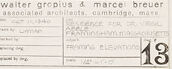
This image is a technical architectural drawing or blueprint. The drawing features various sections and an elevation of a structure. The plans include detailed measurements, indicating the dimensions of rooms and structural elements. There are a few specific labels visible, such as "NORTH ELEVATION" and "SECTION A-A", "SECTION B-B", providing a view of the building from different angles. There is also text at the bottom right that includes possibly the name "Marcel Breuer," indicating the architect or designer associated with this blueprint, as well as some other information such as "DETAIL AT SOUTH ENTRY," "STONE FLOOR," and "WOOD FLOOR." The blueprint has a combination of straight lines, text, and measurements, all annotated clearly for the purpose of construction or understanding the design details of the building being represented. The image has a white background with the drawing and text predominantly in a dark color for contrast.
Created by gpt-4o-2024-05-13 on 2025-03-07
This image displays an architectural technical drawing of the "North Elevation" of a building. The drawing is highly detailed and includes various construction notes, dimensions, and specifications. The main part of the drawing shows the north facade of a building, detailing the layout of windows, doors, and structural components such as beams, studs, and joists. It mentions different floor levels such as the "Main 105 surface floor," "Frame ceiling floor," "Frame first floor," and "Frame basement floor." Below the main elevation drawing, there are two sectional views labeled "Section A-A" and "Section B-B," which provide cross-sectional details of the building structure at specific locations. These sections reveal internal details like wall thicknesses, internal framing elements, and foundation specifics. The bottom right corner of the drawing contains a title block with information about the architects, Walter Gropius & Marcel Breuer, associated with "Architectural Offices, Cambridge, Mass." It includes various project details, the date (August 1, 1937), drawing status (Working Drawing – Not for Construction), and sheet number (18). Overall, the image is a comprehensive technical drawing that architects and construction professionals would use to understand the construction and design details of the north elevation of the building.
Anthropic Claude
Created by claude-3-haiku-20240307 on 2024-12-31
The image appears to be an architectural or engineering blueprint or technical drawing. It contains detailed diagrams, measurements, and technical specifications for a structure or design. The main part of the drawing shows a plan or elevation view, with various labeled sections and dimensions. There are also smaller supplementary drawings, such as a section or elevation view, shown at the bottom of the image. The overall style and content suggest this is a professional technical document rather than a personal sketch or artistic rendering.
Created by claude-3-opus-20240229 on 2024-12-31
The image shows architectural blueprints or plans for what appears to be a residence or house. The plans include detailed diagrams and measurements for framing, foundation, and various structural elements. The title at the bottom reads "Walter Dennis & Maude Denny Residence". The plans are hand-drawn in a technical drafting style on grid paper, typical of architectural drawings before the widespread use of computer-aided design (CAD) software.
Created by claude-3-5-sonnet-20241022 on 2024-12-31
This image appears to be an architectural drawing or blueprint showing various technical sections and elevations. It includes several sectional views labeled as "Section A-A" and "Section B-B" at the bottom of the drawing, along with what appears to be a larger sectional elevation view across the top portion. The drawing is rendered in a typical architectural style with thin lines and dimensional notations. The title block in the lower right corner indicates this is likely from an architectural firm, though the text is somewhat difficult to read in this image quality. The drawing appears to be focusing on structural or interior details of a building component, with various measurements and construction details shown throughout the document.
Meta Llama
Created by us.meta.llama3-2-11b-instruct-v1:0 on 2025-03-17
The image is a technical drawing of a building's floor plan, created by Walter Gropius and Marcel Breuer, two renowned architects. The drawing is a detailed representation of the building's layout, including the location of various rooms, doors, windows, and other architectural features. **Key Features:** * **Floor Plan:** The drawing shows the building's floor plan, which includes the location of various rooms, doors, windows, and other architectural features. * **Architects' Names:** The names of the architects, Walter Gropius and Marcel Breuer, are prominently displayed at the bottom right corner of the drawing. * **Technical Details:** The drawing includes technical details such as measurements, scales, and notations, indicating the level of precision and attention to detail that went into its creation. * **Date and Time:** The date and time of the drawing are not explicitly stated, but based on the style and content, it appears to be from the early 20th century. **Overall Impression:** The image presents a clear and concise representation of the building's floor plan, showcasing the expertise and attention to detail of the architects. The technical details and notations suggest that the drawing was created for a specific purpose, such as construction or renovation. Overall, the image provides valuable insight into the design and planning process of a building, highlighting the importance of technical drawings in architecture.
Created by us.meta.llama3-2-90b-instruct-v1:0 on 2025-03-17
The image depicts a technical drawing of a building's floor plan, likely created by an architect or engineer. The drawing is rendered in black ink on white paper and features various lines, symbols, and notations that provide detailed information about the building's design and layout. **Key Features:** * **Floor Plan:** The central element of the drawing is the floor plan, which shows the layout of the building's rooms, corridors, and other spaces. * **Dimensions:** The drawing includes dimensions and measurements for various elements, such as doorways, windows, and walls. * **Symbols and Notations:** The drawing uses a range of symbols and notations to convey information about the building's design and construction, including materials, finishes, and structural elements. * **Scale:** The drawing is likely drawn to scale, allowing viewers to understand the relative sizes and proportions of the different elements. * **Title Block:** The title block in the bottom-right corner provides information about the project, including the name of the architect, the date, and the project number. **Overall Impression:** The image presents a detailed and technical representation of a building's design, showcasing the careful planning and attention to detail that goes into creating a functional and aesthetically pleasing space. The use of symbols, notations, and dimensions provides a wealth of information about the building's design and construction, making it a valuable resource for architects, engineers, and builders.
Amazon Nova
Created by amazon.nova-lite-v1:0 on 2025-02-26
This image appears to be an architectural blueprint or floor plan. It shows a detailed layout of a building's interior, with various sections and measurements indicated. The blueprint is divided into two main sections, labeled "A-A" and "B-B," which likely represent different elevations or views of the building. The sections are drawn to scale, with precise measurements and dimensions provided. The blueprint includes various lines, labels, and annotations that describe the building's layout, including the placement of walls, doors, windows, and other structural elements. There are also notes and revisions mentioned in the bottom right corner, indicating that this is a working draft or set of plans. Overall, the image provides a comprehensive overview of the building's interior design and layout, allowing architects, engineers, and contractors to visualize and plan the construction or renovation of the space.
Created by amazon.nova-pro-v1:0 on 2025-02-26
The image is a technical drawing of a building. It is a detailed blueprint that includes sections and elevations. The blueprint is divided into two main sections, labeled as Section A-A and Section B-B, each providing a different perspective of the building's structure. The drawing includes measurements, annotations, and specific details about the construction, such as floor levels, wall thicknesses, and door and window placements. The elevation labeled "North Elevation" provides a front view of the building, showing the layout and dimensions of the exterior walls and openings. The blueprint also includes a title block with information about the architect, Walter Gropius & Marcel Breuer, and the associated architect, Cambridge, Mass. The drawing is numbered 13, indicating it is part of a series of blueprints.
Text analysis
Amazon