Machine Generated Data
Tags
Color Analysis
Feature analysis
Amazon

| Monitor | 97.7% | |
Categories
Imagga
| text visuals | 68.2% | |
| streetview architecture | 11.4% | |
| interior objects | 7.6% | |
| cars vehicles | 7.5% | |
| paintings art | 2.2% | |
| food drinks | 1.7% | |
Captions
Microsoft
created by unknown on 2022-06-04
| a flat screen tv sitting on top of a blackboard | 73.2% | |
| a flat screen tv | 73.1% | |
| a flat screen tv sitting on top of a table | 41.4% | |
Clarifai
created by general-english-image-caption-blip on 2025-05-04
| a photograph of a black and white photo of a drawing of a building | -100% | |
OpenAI GPT
Created by gpt-4 on 2024-12-07
This image displays a black and white technical drawing or blueprint. It is a plan view along with multiple sectional views of what appears to be a mechanical or architectural design. The sections are labeled as "Section AA," "Section BB," and "Section CC." Additionally, there are notes at the bottom, which might specify material types, construction methods, or other important details relevant to the drawing. These sorts of drawings are typically used by engineers, architects, or builders as precise guides for constructing or manufacturing a component or structure. There are reference numbers and possibly dates on the drawing, indicating the version or part of a larger set of plans. The image has a black border around it, with the number "91-10" printed in the bottom right corner, likely an identification or catalog number for the drawing.
Created by gpt-4o-2024-05-13 on 2024-12-07
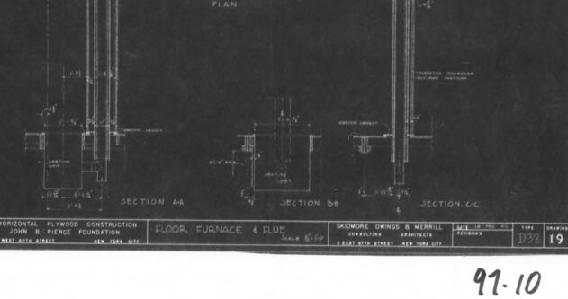
The image depicts a technical drawing, likely an architectural blueprint, for a "Floor Furnace & Flue." The document includes different sections and detailed views:
- The center top features a plan view labeled "Plan."
- Along the left and right sides, there are sectional views labeled "Section A-A," "Section B-B," and "Section C-C."
- Various dimensions and technical specifications are present throughout the blueprint.
- Notable text sections include "Horizontal Plywood Construction" and it mentions the firm "Skidmore, Owings & Merrill" which is located at "14 East 33rd Street, New York, N.Y."
- There is a drawing number at the lower right, identified as "D32" along with a labeled sheet number "19."
- The date noted on the drawing is 1929.
- The lower left corner indicates "U.S. half-size library, Index card No. 97.10," suggesting it’s perhaps a reduced-size copy from a library archive.
The technical intricacy and labeling suggest it is a part of a larger set of construction or architectural plans and likely used for informational or construction purposes.
Anthropic Claude
Created by claude-3-haiku-20240307 on 2024-12-07
The image appears to be a technical drawing or blueprint. It shows cross-sectional diagrams and plans for some kind of construction or engineering project. The plans include detailed measurements and technical specifications, with labels indicating different components such as a "floor furnace" and "flue". The image has a black-and-white, high-contrast appearance, typical of technical drawings or blueprints.
Created by claude-3-5-sonnet-20241022 on 2024-12-07
This is an architectural blueprint or technical drawing showing details of a floor furnace and flue system. The drawing contains multiple sections labeled as "SECTION A-A," "SECTION B-B," and "SECTION C-C," as well as a "PLAN" view. The drawings appear to be rendered as white lines on a dark background, which is typical of blueprint reproduction methods. The document includes various measurements and technical specifications, and appears to be part of a larger set of architectural or engineering documents. In the lower portion of the drawing, there appears to be a title block with project information. The image is framed in what looks like a black border, and has the number "97-10" written in the bottom right corner.
Meta Llama
Created by us.meta.llama3-2-11b-instruct-v1:0 on 2024-12-07
The image is a black-and-white photograph of a technical drawing, likely a blueprint, for a floor furnace and flue system. The drawing is presented on a white sheet of paper, surrounded by a thick black border, and features a horizontal plywood construction with a John R. Pierce Foundation label at the bottom.
Key Features:
- Technical Drawing: The drawing appears to be a blueprint or technical drawing for a floor furnace and flue system.
- Black-and-White Photograph: The image is a black-and-white photograph of the drawing.
- White Sheet of Paper: The drawing is presented on a white sheet of paper.
- Black Border: The drawing is surrounded by a thick black border.
- John R. Pierce Foundation Label: A label at the bottom of the drawing reads "John R. Pierce Foundation."
- Horizontal Plywood Construction: The drawing features a horizontal plywood construction.
- Floor Furnace and Flue System: The drawing appears to be a blueprint for a floor furnace and flue system.
Overall:
The image presents a detailed technical drawing for a floor furnace and flue system, likely used for construction or installation purposes. The drawing is presented on a white sheet of paper with a black border, and features a label from the John R. Pierce Foundation.
Created by us.meta.llama3-2-90b-instruct-v1:0 on 2024-12-07
The image depicts a technical drawing of a floor furnace and flue, presented in a black-and-white format. The drawing is set against a white background, surrounded by a thick black border. In the bottom-right corner, the number "97-10" is handwritten in black ink.
At the bottom of the drawing, a series of small boxes contain text that provides additional information about the design. These boxes are labeled with letters such as "A," "B," and "C," which likely correspond to specific sections or components of the furnace and flue system.
The overall appearance of the image suggests that it is a historical document or archival material, possibly from an architectural or engineering firm. The use of a black-and-white format and the presence of handwritten notes and labels indicate that the image may have been created using traditional drafting techniques rather than modern computer-aided design (CAD) software.
Amazon Nova
Created by amazon.nova-lite-v1:0 on 2025-02-27
This image is a black-and-white photograph of a technical drawing, likely an architectural blueprint or engineering plan. The drawing is framed within a black border, and the image is captured from a top-down perspective. The drawing features a detailed layout of a building's structure, with various sections and annotations.
The drawing includes labels such as "SECTION AA," "SECTION BB," and "SECTION CC," indicating different cross-sectional views of the building. It also includes measurements and dimensions, as well as annotations for specific components like "FLOOR FURNACE & FLUE," "SKIDMORE OWINGS & MERRILL," and "JOHN B. PIERCE FOUNDATION."
The drawing appears to be a technical plan for a construction project, possibly related to a building's foundation or structural elements. The inclusion of the architect's name, "SKIDMORE OWINGS & MERRILL," suggests that this is an official document from the architectural firm responsible for the design.
Overall, the image provides a glimpse into the technical details and planning involved in a construction project, showcasing the intricate layout and specifications required for such a complex undertaking.
Created by amazon.nova-pro-v1:0 on 2025-02-27
The image is a framed architectural blueprint, specifically a horizontal plywood construction drawing. The blueprint is labeled with "SECTION A-A," "SECTION B-B," and "SECTION C-C," indicating different sections of the construction plan. The drawing includes details of a floor furnace and flue, suggesting it is a plan for a heating system installation or modification. The document is attributed to "John B. Pierce Foundation" and "Skimore, Owings & Merrill," with a date of "1972." The blueprint is marked with a reference number "97-10" at the bottom right corner.
Google Gemini
Created by gemini-2.0-flash-lite on 2025-04-28
This is a technical drawing, likely an architectural blueprint or similar technical illustration. The drawing appears to be a plan and sections of a "Floor Furnace & Flue" construction. The blueprint displays a detailed view of the structure, with labelled sections "Section A-A," "Section B-B," and "Section C-C." Also noted in the blueprint are:
- Project: The drawing relates to a "Horizontal Plywood Construction" for the "John B. Pierce Foundation."
- Architects: The consulting architects are listed as "Skidmore, Owings & Merrill."
- Location: The address is identified as "8 East 45th Street, New York City."
- Drawing Details: A drawing type is listed as "D32," with the number "19" possibly indicating a specific drawing number or revision.
- Scale: "Scale: 1/4"=1'-0"
- Date: The date is not visible, but the number "97-10" at the bottom could be a reference number or filing code.
The drawing style is typical of technical blueprints, using lines, annotations, and dimensioning to represent the design of the structure in detail.
Created by gemini-2.0-flash on 2025-04-28
Here's a description of the image:
The image is a black and white photograph of what appears to be an architectural or engineering drawing. The drawing is labeled as a "Floor Furnace & Flue" and features several sections labeled "Section AA," "Section BB," and "Section CC," along with a "Plan."
The layout includes technical details, cross-sections, and specifications for the furnace and flue system, common elements of architectural blueprints. It is likely a technical document meant for construction or installation purposes.
The drawing itself is surrounded by a white border, which is in turn framed by a thicker black border of the photograph. At the bottom right, there are numbers "D32 19" and "97-10," potentially indicating the drawing's ID and archival number. The names "Skidmore Owings & Merrill" are mentioned in the drawing, which could indicate the architectural firm responsible.
Mistral Pixtral
Created by us.mistral.pixtral-large-2502-v1:0 on 2025-04-28
The image is a framed black-and-white architectural drawing or blueprint. The drawing appears to depict the horizontal pitwood construction of a furnace and flue, likely for a building. The blueprint is divided into several sections labeled as "Section AA," "Section BB," and "Section CC," each showing different cross-sectional views of the construction.
Key features of the drawing include:
Sections and Plans:
- The blueprint includes a plan view in the middle, flanked by three cross-sectional views labeled AA, BB, and CC.
- These sections show the internal structure and layout of the furnace and flue.
Details and Measurements:
- The drawing includes various annotations and measurements, indicating specific dimensions and structural details.
- There are labels and notes that provide information about different parts of the construction.
Architectural Firm:
- The blueprint is credited to "Shawmut Owners & Werrill," an architectural firm.
- The address of the firm is noted as "6 East 47th Street, New York City."
Drawing Information:
- The drawing is labeled with a scale of "Scale 3/16" = 1'-0".
- It is dated April 1924, indicating when the drawing was created.
- There is a drawing number "D32 19" and a reference number "97-10" at the bottom right.
Framing:
- The blueprint is framed with a black border and a white mat, which helps to highlight the drawing itself.
Overall, the image provides a detailed technical drawing of a furnace and flue construction, showcasing the intricate design and structural elements involved in the architecture.
Text analysis
Amazon