Machine Generated Data
Tags
Color Analysis
Feature analysis
Amazon
Clarifai
AWS Rekognition
| Document | 85.1% | |

Categories
Imagga
created on 2018-03-22
| text visuals | 99.8% | |
| paintings art | 0.2% | |
Captions
Microsoft
created by unknown on 2018-03-22
| a close up of text on a white background | 76.3% | |
| a close up of text on a black background | 70.2% | |
| a close up of text on a white surface | 70.1% | |
Clarifai
No captions written
Salesforce
Created by general-english-image-caption-blip on 2025-05-11
a photograph of a drawing of a plan for a house
Created by general-english-image-caption-blip-2 on 2025-06-28
a drawing of a building with plans and drawings
OpenAI GPT
Created by gpt-4 on 2025-03-08
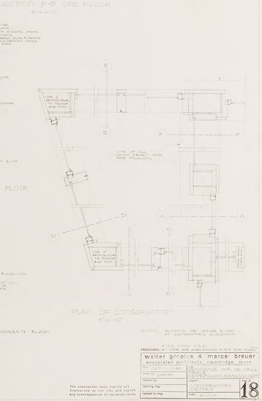
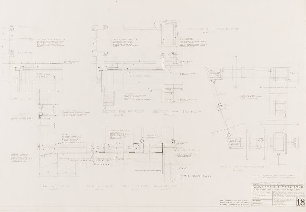
The image is a technical drawing or architectural blueprint consisting of several detailed cross-sections and plans of a building. The sections include labels such as "SECTION B-B", "SECTION C-C", "SECTION E-E AT ROOF", and "SECTION F-F 2nd FLOOR", among others. There are also detailed notes and dimensions for various building components, such as walls, floors, ceilings, and other structural elements.
There are annotations for specific materials and construction techniques, which are common in architectural plans to guide the construction process. The drawing is laid out in an organized manner with each section carefully labeled and dimensioned.
On the bottom right of the drawing, there's a title block with text that is difficult to discern at this resolution, but typically this area includes information like the project title, architects' names, scale, drawing number, and possibly the date. The drawing is meticulous and precise, suggesting it's meant for professional use in the building process.
Created by gpt-4o-2024-05-13 on 2025-03-08
This image is an architectural drawing or blueprint. The drawing includes detailed diagrams and sections of a building design. Specific sections are labeled with letters such as B-B, C-C, E-E, and A-A, indicating different views and cross-sections of the structure. These sections show various elevations, floor levels, and structural components, with detailed annotations regarding materials, measurements, and construction techniques.
The drawing displays a plan of a conservatory along with sections of floors, walls, and roof areas. The layout includes notes on elements such as plaster, concrete blocks, and woodwork, providing specifics on their dimensions and placement.
At the bottom right corner, there is an information box with names of the architects Walter Gropius and Marcel Breuer, their associate architectural firm in Cambridge, Massachusetts, and a project title labeled "Franklin D. Roosevelt HOUSING." There is also a reference to a sheet number "18," indicating it is part of a larger set of architectural plans.
Anthropic Claude
Created by claude-3-haiku-20240307 on 2024-12-30
This image appears to be an architectural or engineering drawing or blueprint. It contains various detailed technical diagrams, measurements, and annotations that seem to be related to the design or construction of a structure or device. The drawing includes multiple views, sections, and perspectives, providing comprehensive technical information about the subject matter. Overall, this image depicts a highly detailed and technical engineering or architectural plan.
Created by claude-3-opus-20240229 on 2024-12-30
The image shows architectural drawings or blueprints. It consists of detailed plans and cross-sections of what appears to be a building structure, likely a house or residential property based on the room labels and layout. The plans include measurements, material specifications, and construction details drawn using thin, precise lines on a plain white background. The bottom right corner includes a title block with project information, although the text is too small to read clearly in this image resolution.
Created by claude-3-5-sonnet-20241022 on 2024-12-30
This appears to be an architectural drawing or blueprint showing various cross-sectional details of a building. The image contains multiple technical sections and elevations with detailed measurements and annotations. The drawing appears to be done in pencil or light ink on paper, showing different architectural elements like floors, walls, and structural components. At the bottom of the drawing, there is a title block which is typical of architectural drawings, and the sheet appears to be numbered "18". The drawing style is precise and technical, with multiple views showing different parts of what seems to be the same structure from various angles and perspectives. The lines are clean and professional, demonstrating standard architectural drawing conventions.
Created by us.anthropic.claude-3-5-sonnet-20241022-v2:0 on 2025-06-26
This image appears to be an architectural drawing or blueprint showing various cross-sectional details of a building. The drawing includes multiple section views labeled with letters (like "Section A-A," "Section B-B," etc.) and contains detailed construction information with dimensions and annotations. The drawing is done in a technical style typical of architectural documentation, with thin lines showing wall assemblies, structural elements, and other building components. At the bottom of the sheet, there appears to be a title block with what looks like architectural firm information. The overall layout is organized in a grid-like pattern with different sections distributed across the page. The drawing appears to be focusing on specific construction details and connections within the building's design.
Meta Llama
Created by us.meta.llama3-2-11b-instruct-v1:0 on 2025-03-15
The image presents a detailed architectural drawing, specifically a floor plan, showcasing the layout and design of a building or structure. The drawing is rendered in black ink on white paper, with various sections and details labeled throughout.
Key Features:
- Floor Plan: The drawing depicts the ground floor of a building, with several rooms and spaces outlined.
- Section Labels: Various sections are labeled, including "SECTION E-E ST ROOF," "SECTION A-A 2ND FLOOR," and "SECTION B-B," indicating different levels or areas of the building.
- Dimensions: Measurements are provided in inches, with some dimensions extending beyond the edges of the paper.
- Labels and Annotations: Small labels and annotations are scattered throughout the drawing, likely indicating specific features, materials, or details about the building's design.
- Scale: A scale is provided in the bottom-right corner, allowing for accurate measurements and scaling of the drawing.
- Date and Signature: The date "1/23/64" is written in the bottom-right corner, along with a signature that is illegible due to the image quality.
- Additional Text: Additional text is present at the bottom of the page, although it is too small and blurry to decipher.
Overall Impression:
The drawing appears to be a detailed and precise representation of the building's floor plan, with a focus on showcasing the layout and design of the structure. The use of labels, annotations, and dimensions suggests that the drawing is intended for architectural or engineering purposes, possibly for construction or renovation projects.
Created by us.meta.llama3-2-90b-instruct-v1:0 on 2025-03-15
This image presents a detailed architectural drawing, likely a blueprint or technical illustration, showcasing various sections of a building's design. The drawing is rendered in black ink on a white background, with numerous lines, symbols, and annotations that provide specific information about the structure's layout and features.
The drawing appears to be a composite of several different sections, each labeled with a unique identifier (e.g., "SECTION E-F 2ND FLOOR"). These sections are arranged in a collage-like fashion, allowing the viewer to visualize the building's overall design and how its various components fit together.
In the bottom-right corner of the image, a small box contains text that reads "Walter Gropius & marce breuer associated architects cambridge, mass." This suggests that the drawing was created by the renowned architectural firm of Walter Gropius and Marcel Breuer, who were known for their innovative and influential designs in the early 20th century.
Overall, this image provides a fascinating glimpse into the world of architectural design and the meticulous attention to detail required to bring a building project to life.
Amazon Nova
Created by amazon.nova-lite-v1:0 on 2025-01-12
The image is a technical drawing of a building, likely a conservatory, with detailed sections and notes. The drawing includes various sections labeled from A to F, indicating different parts of the building. Each section provides a detailed view of the structure, including dimensions and annotations. The sections show the layout of the building, including walls, floors, and possibly windows or doors. The drawing also includes notes and measurements, which are essential for construction and understanding the building's design. The overall layout suggests a modern architectural design, possibly with a focus on natural light and open spaces.
Created by amazon.nova-pro-v1:0 on 2025-01-12
The image shows a detailed architectural plan of a building, possibly a conservatory or a similar structure. The plan is divided into several sections, each labeled with a letter and number combination, such as "SECTION D-D" and "SECTION B-B." The sections depict different elevations and cross-sections of the building, showcasing the layout, dimensions, and structural elements. The plan includes measurements, annotations, and notes, indicating the design intent and construction details. The overall design appears to be a modern and functional structure, with a focus on natural light and open spaces.
Google Gemini
Created by gemini-2.0-flash on 2025-05-12
Here is a description of the image:
The image is a detailed architectural blueprint or drawing, rendered in a pale gray color with handwritten annotations throughout. It appears to be a plan for a building, with multiple sections and views presented on the same sheet.
Key elements include:
Sections: Labeled sections such as "SECTION F-F 2ND FLOOR", "SECTION E-E AT ROOF", "SECTION A-A 2ND FLOOR", "SECTION D-D", "SECTION C-C", "SECTION B-S", and "SECTION A-A". These sections provide detailed vertical cuts through different parts of the structure.
Plan View: A plan view labeled "PLAN OF CONSERVATORY". This provides a top-down perspective of the building's layout.
Technical Drawings: The blueprint contains precise lines, dimensions, and symbols to indicate construction details, materials, and specifications. There are various measurements and notes written in small handwriting, indicating specific features and components.
Annotations: The drawing is densely annotated with handwritten labels and descriptions. These notes provide detailed instructions or specifications for the construction.
Text and Title Block: In the lower right corner, there is a title block with the text "walter groplus & marce breuer associated architects, cambridge". Below this, there is also a numbering for the page.
Overall, the image is a technical and detailed architectural drawing intended to provide a comprehensive guide for the construction of a building.
Created by gemini-2.0-flash-lite on 2025-05-12
This image is an architectural blueprint, likely a section and plan of a building, focusing on the conservatory. It's a technical drawing filled with lines, labels, and dimensions, characteristic of architectural plans. Key elements include:
- Multiple Sections: There are several section views labeled "SECTION E-E", "SECTION F-F", "SECTION A-A", "SECTION D-D", "SECTION C-C", and "SECTION B-B" that show different cross-sections of the structure.
- Plan View: There's a "PLAN OF CONSERVATORY" that illustrates a top-down view, showing the layout of the conservatory.
- Annotation: The blueprint is densely packed with handwritten annotations providing details on materials, dimensions, and construction techniques.
- Scale: The scale is indicated in the section titles.
- Architectural Style: The architectural design is a modern, minimalist aesthetic.
- Professional Information: There is a title block with "Walter Gropius & Marcel Breuer" who were associated architects in Cambridge, Massachusetts.
In general, the image gives a detailed technical look at the architectural design and construction of a building.
Mistral Pixtral
Created by us.mistral.pixtral-large-2502-v1:0 on 2025-05-30
The image is an architectural drawing, specifically a set of construction details. It appears to be a detailed section drawing of a building, showing various structural and finishing elements. Here are the key elements and details visible in the drawing:
Title Block: Located at the bottom right corner, it includes information such as the architects' names (Walter Gropius & Marcel Breuer), the project name (Pennsylvania Pavilion), and the drawing number (18). It also includes the scale of the drawing and other relevant project information.
Sections and Details: The drawing shows multiple sections and details of the building, including:
- Section E-E: This section seems to focus on the roof structure and its connection to the walls.
- Section F-F: This section appears to show the roof edge and gutter details.
- Section G-G: This section seems to illustrate the clay floor and its connection to other elements.
- Section H-H: This section shows the concrete slab and its details.
- Section I-I: This section appears to detail the intersection of the roof with the walls.
Annotations and Dimensions: The drawing includes various annotations and dimensions that specify the sizes and locations of different elements. These annotations are crucial for construction purposes, providing precise measurements and details for builders.
Materials and Finishes: The drawing indicates different materials and finishes used in the construction, such as concrete, clay, and metal. These are essential for understanding the structural integrity and aesthetic finish of the building.
Structural Elements: The drawing shows various structural elements like beams, columns, and slabs, which are essential for the stability and strength of the building.
Overall, this architectural drawing provides a comprehensive view of the structural and finishing details of a building, essential for its construction and understanding of its design.
Qwen
Created by Qwen/Qwen2.5-VL-7B-Instruct on 2025-07-20
This image appears to be an architectural or engineering drawing, likely a set of detailed plans and sections for a specific project. The drawing includes several labeled sections and a plan of a conservatory. Here are the key elements visible in the image:
Sections (e.g., F-F 2nd Floor, E-E at Roof, A-A 2nd Floor, B-B, C-C, B-B, A-A, B-B): These sections show detailed cross-sectional views of the structure, likely focusing on the 2nd floor and the roof. Each section is meticulously labeled with dimensions, materials, and construction details, including annotations for specific parts such as insulation, wall types, and framing. The labels and notes are detailed, indicating the exact placement and specifications of the elements.
Plan of Conservatory: In the bottom right corner, there is a plan view of a conservatory, which is a type of greenhouse or sunroom often attached to a main building. This plan includes dimensions and layout details, suggesting the conservatory's placement in relation to the main structure.
Text and Annotations: The drawing is filled with text and annotations, providing specific measurements and construction notes. These annotations likely include information on the materials used, such as types of wood, insulation, and the type of glass, as well as construction techniques.
Scale: The drawing includes a scale, which is crucial for understanding the size and proportions of the elements depicted.
Architectural Firm: The bottom right corner includes the name of the architectural firm, "Walter Gropius & Marcel Breuer, Associated Architects, Cambridge, Mass."
This type of drawing is typically used in the planning and construction phase of a building project to ensure that all elements of the structure are accurately designed and constructed according to the specified details and specifications.
Created by Qwen/Qwen2.5-VL-72B-Instruct on 2025-07-20
This image is an architectural drawing, specifically a section drawing and plan of a conservatory, designed by Walter Gropius and Marcel Breuer. The drawing is detailed and includes various sections such as:
- Section A-A: 2nd Floor
- Section B-B: 2nd Floor
- Section C-C: 2nd Floor
- Section D-D: 2nd Floor
- Section E-E: At Roof
The drawing includes dimensions, notes, and specifications for the construction of the conservatory. The plan of the conservatory is also shown, indicating the layout and arrangement of the space. The drawing is labeled as "CONSERVATORY DETAILS" and is numbered 18. The precision and detail suggest that this is a professional architectural document used for construction purposes.
Text analysis
Amazon