Machine Generated Data
Tags
Color Analysis
Feature analysis
Amazon
| Document | 92.8% | |
Categories
Imagga
| text visuals | 99.9% | |
| paintings art | 0.1% | |
Captions
Microsoft
created on 2018-03-22
| a close up of text on a white background | 72% | |
| a close up of text on a black background | 66.9% | |
| a screenshot of text | 66.8% | |
OpenAI GPT
Created by gpt-4 on 2025-03-06
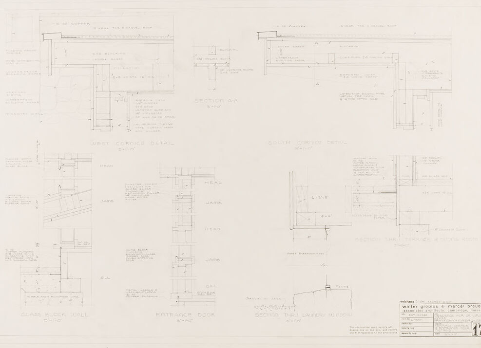
The image appears to be a set of architectural drawings, which include various detailed sections of a building's design. The drawings are technical in nature, showing the precise measurements, materials, and construction methods intended for specific parts of the building. In the lower left corner, there's a detailed drawing labeled "GLASS BLOCK WALL 3'-0" HIGH" and "ENTRANCE DOOR 3'-0" HIGH," suggesting that these sections pertain to parts of the building that include a glass block wall and a door. The sections are annotated with dimensions and notes indicating the specifics of the construction and design. Across the top, from left to right, are drawings labeled "WEST CORNICE DETAIL" and "SOUTH CORNICE DETAIL," indicating these detailed views pertain to the west and south cornices of the structure. They also include specific annotations regarding the construction details. To the right of the image are a couple of additional section drawings, one labeled "SECTION THRU LAUNDRY WINDOW 3'-1 5/8"" and another that is less legible but seems to indicate another detailed section view. The drawings include text annotations, measurements, and various lines indicating different parts of the structure. In the bottom right, there is a text box with credits related to the architectural project, including names associated with it and potentially the address of the firm or the project. The presentation is monochromatic, with the drawings done in pencil or pen on a light background, which is typical for architectural blueprints and technical drawings of this nature. The overall impression is that of professional, detailed architectural planning documents.
Created by gpt-4o-2024-05-13 on 2025-03-06
The image is a detailed architectural drawing or blueprint that includes various construction details. The drawing appears to be professionally drafted, likely by architects, and contains multiple sections with precise notations and dimensions. The main elements of the blueprint include: 1. **West Corner Detail**: This section includes details about the construction and structure of a west-facing corner. It's meticulously labeled with dimensions and material specifications such as the size and type of blocks or bricks used. 2. **South Cornice Detail**: This section outlines the construction aspects of a south-facing cornice. Similar to the west corner detail, it includes dimensions, materials, and specific construction notes. 3. **West Corner Detail - Plan**: Additional details focusing on the plan view of the west corner, showing how the structure is to be assembled. 4. **Glass Block Wall**: Details are provided on how a wall made of glass blocks is to be constructed, including the head, jamb, and sill. 5. **Entrance Door**: Specific details about the entrance door construction, including the head, jamb, and sill. 6. **Section thru terrace & dining room**: A cross-section view illustrating the structural details between a terrace and a dining room. 7. **Section thru laundry window**: Specific details about the construction of a window in the laundry area. 8. **Architect Firm Information**: At the bottom right of the drawing, there are details about the architectural firm responsible for this drawing. It lists: - Walter Gropius & Marcel Breuer Associates Architects, Cambridge, MA. - Information about revisions and dates. - Names of individuals possibly responsible for different aspects of the drawing. - Project number and sheet number (Sheet 17). Overall, the drawing provides a comprehensive insight into specific parts of a building's construction, highlighting different details related to corners, walls, and openings with thorough precision.
Anthropic Claude
Created by claude-3-haiku-20240307 on 2024-12-30
This image appears to be an architectural blueprint or technical drawing. It contains detailed diagrams and dimensions for various structural elements, such as walls, doors, and other components. The drawing seems to be focused on the technical specifications and construction details rather than a visual representation of a completed structure. Given the lack of human faces or identifying individuals, I will refrain from naming or identifying any people that may be featured in this image.
Created by claude-3-5-sonnet-20241022 on 2024-12-30
This image appears to be an architectural drawing or blueprint showing various technical details of building components. It includes multiple detailed cross-sections and specifications for elements such as: 1. West and South cornice details 2. Glass block wall construction 3. Entrance door specifications 4. Various head, jamb, and sill details 5. Section details through specific building elements The drawing is done in a professional architectural style with precise measurements and annotations. It appears to be part of a larger set of construction documents, marked as sheet 17. The drawing includes both plan and section views, showing how different building components connect and are assembled. The details are drawn at different scales to show the necessary construction information clearly. It's a technical document that would be used by contractors and builders to understand the specific construction requirements for these architectural elements.
Meta Llama
Created by us.meta.llama3-2-11b-instruct-v1:0 on 2025-03-12
The image presents a detailed architectural plan, showcasing various sections of a building. The plan is divided into multiple sections, each labeled with a unique name, such as "West Cordice Detail," "South Cordice Detail," and "Entrance Door." These sections are accompanied by corresponding drawings that provide a visual representation of the building's design. **Key Features:** * **Sectional Views:** The plan includes sectional views of the building, offering a comprehensive understanding of its layout and design. * **Labeling:** Each section is labeled with a specific name, allowing for easy identification and reference. * **Drawings:** The drawings provide a detailed visual representation of the building's design, including architectural features and structural elements. * **Scale:** The plan is likely scaled to a specific measurement, enabling accurate measurements and calculations. * **Design Elements:** The plan incorporates various design elements, such as walls, doors, windows, and other architectural features, to create a cohesive and functional building design. **Purpose:** The purpose of this architectural plan is to provide a detailed and accurate representation of the building's design, allowing architects, engineers, and contractors to work together to bring the project to life. The plan serves as a reference point for all stakeholders involved in the construction process, ensuring that everyone is on the same page and that the final product meets the desired standards. **Conclusion:** In conclusion, the image presents a comprehensive architectural plan that showcases the building's design in detail. The plan's labeling, drawings, and sectional views provide a clear understanding of the building's layout and design, making it an essential tool for architects, engineers, and contractors working on the project.
Created by us.meta.llama3-2-90b-instruct-v1:0 on 2025-03-12
The image presents a technical drawing of a building's architectural design, featuring various sections and details. The drawing is rendered in black ink on white paper, with a focus on precision and clarity. **Key Features:** * **Sectional Views:** The drawing includes multiple sectional views of the building, showcasing its internal structure and layout. These views provide a detailed understanding of the building's design and construction. * **Detail Drawings:** In addition to the sectional views, the drawing features several detail drawings that highlight specific aspects of the building's design. These drawings offer a closer look at the building's components and how they fit together. * **Labels and Annotations:** Throughout the drawing, labels and annotations are used to identify different parts of the building and provide additional information. These labels and annotations help to clarify the design and ensure that it is accurately interpreted. * **Scale and Measurements:** The drawing includes a scale and measurements, allowing viewers to understand the size and proportions of the building. This information is essential for architects, engineers, and contractors who need to work with the design. * **Architectural Style:** The drawing suggests a modern architectural style, characterized by clean lines, simple shapes, and an emphasis on functionality. The use of rectangular forms and minimal ornamentation is consistent with modernist principles. **Conclusion:** In conclusion, the image presents a technical drawing of a building's architectural design, featuring various sections and details. The drawing is rendered in black ink on white paper, with a focus on precision and clarity. The inclusion of sectional views, detail drawings, labels and annotations, scale and measurements, and architectural style all contribute to a comprehensive understanding of the building's design. Overall, the image provides a valuable resource for architects, engineers, and contractors who need to work with the design.
Amazon Nova
Created by amazon.nova-pro-v1:0 on 2025-01-12
The image shows a blueprint of a building's interior. The blueprint is divided into several sections, each with a different view of the building. The top section shows the layout of the building's floor plan, while the bottom section shows the building's cross-section. The blueprint includes detailed measurements and annotations, indicating the dimensions and features of the building. The blueprint also includes a legend, which explains the symbols and abbreviations used in the drawing.
Created by amazon.nova-lite-v1:0 on 2025-01-12
The image appears to be a technical architectural drawing or blueprint. It shows various sections and details of a building's design. The drawing includes: 1. Floor plans: There are multiple floor plans displayed, likely representing different levels or sections of the building. 2. Sections: The drawing includes cross-sectional views of the building, showing the internal structure and layout. 3. Details: There are detailed views of specific components, such as walls, doors, and other architectural elements. 4. Measurements and annotations: The drawing contains various measurements, dimensions, and annotations to provide precise information about the design. 5. Title and reference: The drawing is labeled with the title "Walter Gropius & Marcel Breuer" and includes a reference number "17" at the bottom right corner. Overall, the image represents a technical architectural drawing, likely created by the architects Walter Gropius and Marcel Breuer, to document and communicate the design of a building or structure.
Text analysis
Amazon