Machine Generated Data
Tags
Color Analysis
Feature analysis
Amazon
| Document | 77.5% | |
Categories
Imagga
| text visuals | 97.5% | |
| paintings art | 2.3% | |
| food drinks | 0.1% | |
| streetview architecture | 0.1% | |
| interior objects | 0.1% | |
Captions
Microsoft
created on 2018-03-22
| a close up of text on a whiteboard | 73.5% | |
| a close up of a whiteboard | 72.7% | |
| close up of text on a whiteboard | 70.1% | |
OpenAI GPT
Created by gpt-4 on 2025-03-07
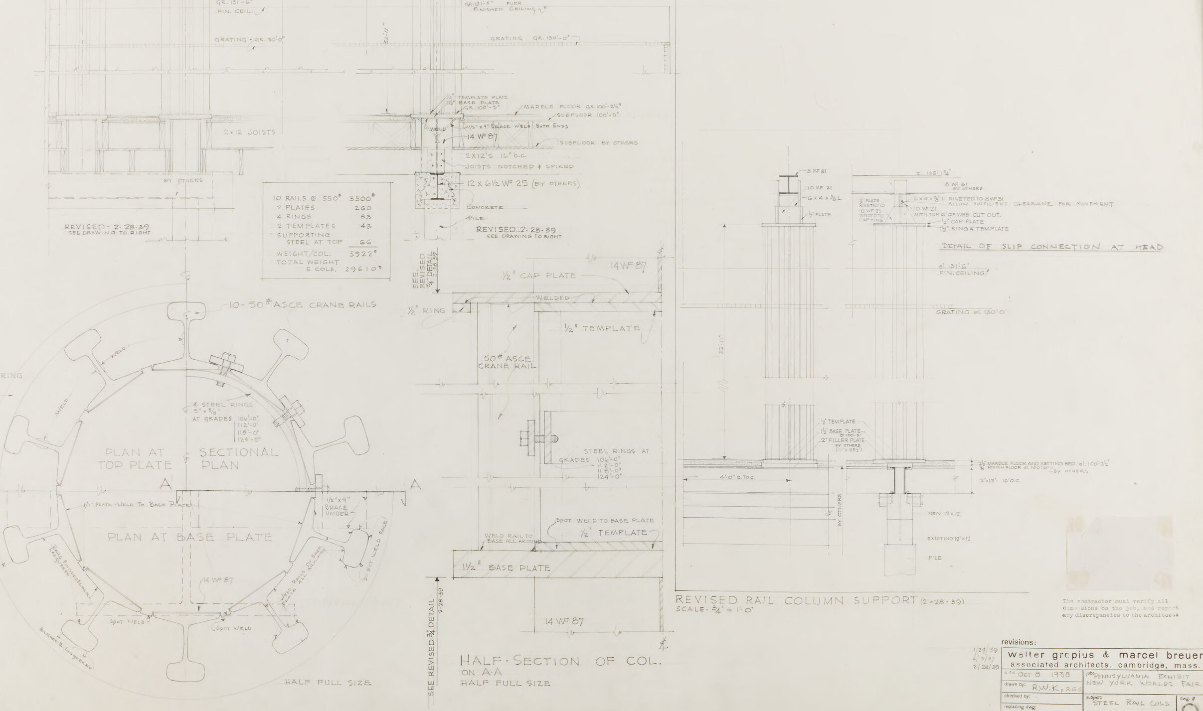
This image displays an architectural drawing or blueprint showing detailed plans and sections of a structure. The drawing includes various views and details such as elevations, sectional plans, and component details. It contains annotations, measurements, and material specifications that are typical components of a technical construction document.
In the center of the image is a circular plan labeled "SECTIONAL PLAN," flanked by "PLAN AT TOP PLATE" and "PLAN AT BASE PLATE." Various other notes detail structural elements like joists and plates, with specific instructions on sizes, dimensions, and materials. On the right side of the drawing, you can see the title "REVISED RAIL COLUMN SUPPORT," indicating that this part of the drawing has been updated from a previous version.
The sheet is covered with hand-written notes, dimensions, and cross-hatching to indicate materials, with various revisions marked by dated stamps or handwritten notes, suggesting that this is a working document that has been used and adjusted during the planning process.
On the bottom right, there appears to be a small label or stamp with some text that may provide information about the project or the architects, but it's too small to read clearly.
This type of drawing is essential for construction and indeed for any form of manufacturing or design where precise specifications are necessary.
Created by gpt-4o-2024-05-13 on 2025-03-07
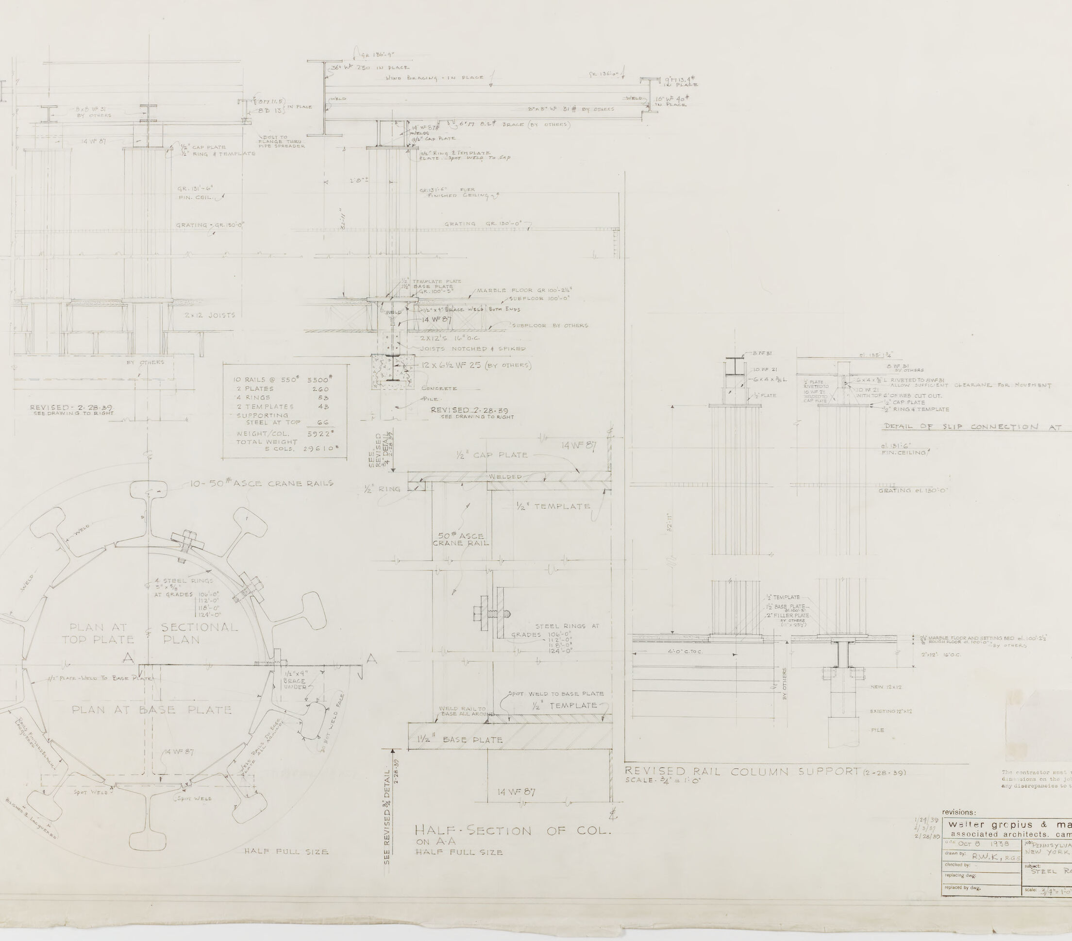
The image appears to be an architectural or engineering technical drawing with multiple detailed plans and sectional views related to a structural component, possibly a rail column support as noted in one section of the drawing.
Key features and elements in the drawing include:
Sectional View: A section labeled "Sectional Plan" and "Half-Section of Col." showing detailed dimensions and construction elements, likely for a column or support structure.
Plan Views: There are top and base plan views of a structural component that look cylindrical in shape, indicated by circular elements and labeled "PLAN AT TOP PLATE" and "PLAN AT BASE PLATE."
Details and Notes: Numerous annotations and notes detailing dimensions, materials, construction techniques, and specific part references. For example, there are specifications for the sizes and placements of plates, bolts, and other structural parts.
Revision Information: The bottom right corner shows a revision area with dates (e.g., 8-28-59) and names (e.g., mjb), alongside the note "REVISED RAIL COLUMN SUPPORT."
Project Information: The drawing title block, which is partially visible, contains the architects' names "Walter Gropius & Marcel Breuer" and the location "Architects Collaborative Inc., Cambridge, Mass."
Technical Specifications: Numerous measurements and technical specifications are included, such as thicknesses, lengths, and material types (e.g., concrete, steel plates).
Detail Views: There is a detailed view labeled "DETAIL OF SUB CONNECTION AT HEAD LINE" providing focused information on a specific part of the structure.
This detailed technical drawing is likely intended for use by engineers, architects, or construction professionals involved in erecting a specific structural element of a building or infrastructure project.
Anthropic Claude
Created by claude-3-haiku-20240307 on 2024-12-30
This image appears to be an engineering or architectural schematic drawing. It contains various technical diagrams, plans, and detailed specifications for what seems to be a structural or mechanical design. The drawing includes multiple views, sections, and dimensions, suggesting it is a comprehensive set of detailed plans or blueprints. There are no human figures or faces present in this image.
Created by claude-3-opus-20240229 on 2024-12-30
The image shows architectural plans and drawings for what appears to be a revised section or portion of a building column. The plans include detailed measurements, notes, and schematics showing various views and cross-sections of the structural elements. At the top, a title indicates this is a "Half Section of Column 5 (Revised)". Below the main drawings are a plan view labeled "Plan at Base Plate" and an elevation view. The plans have handwritten markings and revisions on them. In the bottom right corner is a title block with project information, including the architect's name Walter Gropius & Marcel Breuer.
Created by claude-3-5-sonnet-20241022 on 2024-12-30
This is an architectural or engineering drawing showing various technical details and specifications. The drawing includes multiple views:
- A circular plan view showing what appears to be a crane rail system with radial elements
- A half-section detail of a column assembly
- Several smaller detailed sections showing connections and supports
- Various dimensional notations and technical specifications
The drawing appears to be professionally drafted, with clear line work and annotations. It includes both plan and sectional views, typical of construction or fabrication documents. In the bottom right corner, there's a title block which is standard for architectural and engineering drawings.
The scale is noted as "HALF FULL SIZE" for some of the details, and the drawing shows careful attention to structural connections and assembly details. This appears to be a working drawing, possibly for a specialized piece of industrial or architectural equipment.
Meta Llama
Created by us.meta.llama3-2-11b-instruct-v1:0 on 2025-03-13
The image displays a technical drawing of a building plan, likely created by an architect or engineer. The drawing is on a large sheet of paper, with the edges slightly torn and stained.
- Title and Date
- The title of the drawing is not visible, but it appears to be a building plan for a specific structure.
- The date of the drawing is not visible, but it may have been created in the early 20th century based on the style of the drawing and the materials used.
- Layout and Scale
- The drawing is divided into several sections, each representing a different aspect of the building's design.
- The sections include floor plans, elevations, and cross-sections of the building.
- The scale of the drawing is not explicitly stated, but it appears to be in inches or feet.
- Details and Annotations
- The drawing includes numerous details and annotations, such as measurements, notes, and symbols.
- These details provide information about the building's design, materials, and construction methods.
- Some of the annotations appear to be handwritten, while others may have been added using a pen or pencil.
- Style and Technique
- The drawing style is traditional, with a focus on precision and accuracy.
- The technique used to create the drawing is likely manual, with the artist using a variety of tools and materials to produce the final product.
- The drawing may have been created using a combination of drafting techniques, including freehand drawing and the use of templates and stencils.
- Overall Impression
- The drawing conveys a sense of professionalism and attention to detail.
- The level of precision and accuracy suggests that the drawing was created for a specific purpose, such as construction or renovation.
- The drawing may have been used as a reference for builders, contractors, or other stakeholders involved in the project.
In summary, the image displays a technical drawing of a building plan, created using traditional techniques and materials. The drawing includes numerous details and annotations, providing information about the building's design, materials, and construction methods. The level of precision and accuracy suggests that the drawing was created for a specific purpose, such as construction or renovation.
Created by us.meta.llama3-2-90b-instruct-v1:0 on 2025-03-13
The image depicts a technical drawing, likely an architectural or engineering blueprint, featuring various sections and details of a structure. The drawing is presented in black ink on a white background, with a mix of handwritten notes and printed text.
Key Features:
- Sectional Plan: A circular section of the plan is visible at the bottom left, labeled "SECTIONAL PLAN" and "PLAN AT BASE PLATE." This section appears to be a detailed view of the base plate area.
- Half-Section of Column: The center of the drawing shows a half-section of a column, labeled "HALF-SECTION OF COL." This section provides a detailed view of the column's internal structure.
- Revised Rail Column Support: The right side of the drawing features a revised rail column support section, labeled "REVISED RAIL COLUMN SUPPORT." This section includes detailed measurements and annotations.
- Annotations and Notes: Throughout the drawing, there are numerous handwritten notes and annotations, providing additional information about the structure's design and construction.
- Scale and Measurements: The drawing includes scale markings and measurements, allowing for accurate interpretation of the design.
Overall Impression:
The image presents a detailed and technical drawing of a structure, likely a building or bridge. The use of different sections and views provides a comprehensive understanding of the design and construction of the structure. The inclusion of handwritten notes and annotations adds a personal touch to the drawing, suggesting that it may have been created by an individual or a small team of designers.
Amazon Nova
Created by amazon.nova-lite-v1:0 on 2025-02-25
This image shows a technical drawing of a column support system. The drawing includes a plan view at the top plate, a sectional plan, and a half-section view of the column support. The drawing also includes measurements and specifications for the column support system, including the size and type of steel used, the spacing of the bolts, and the dimensions of the base plate. The drawing is labeled "Revised Rail Column Support" and includes a revision date of 2/28/93. The drawing is attributed to Walter Grepius and Marcel Breuer, Associates Architects, Cambridge, Mass.
Created by amazon.nova-pro-v1:0 on 2025-02-25
The image is a technical drawing of a structure, likely a building or a part of a building. It consists of several sections, each detailing different aspects of the structure. The drawing includes measurements, annotations, and various architectural elements such as columns, beams, and floor plans. The top section shows a detailed plan view, while the bottom section includes a sectional view and a half-section of a column. The annotations provide specific dimensions and notes related to the construction materials and methods.
Text analysis
Amazon