Machine Generated Data
Tags
Color Analysis
Categories
Imagga
| text visuals | 99% | |
| paintings art | 0.5% | |
| food drinks | 0.2% | |
| nature landscape | 0.2% | |
Captions
Microsoft
created by unknown on 2018-03-22
| a close up of text on a white surface | 71.2% | |
| a close up of text on a white background | 69.3% | |
| close up of text on a white surface | 67.4% | |
Clarifai
created by general-english-image-caption-blip on 2025-05-11
| a photograph of a drawing of a plan for a house | -100% | |
OpenAI GPT
Created by gpt-4 on 2025-03-08
The image depicts a technical drawing or plan that appears to be a part of an architectural or engineering document. It is rendered on a grid background which aids in the scaling of dimensions. The drawing itself is very sparse with a lot of white space. There are a few notations, numerical indications, and small detailed elements that suggest measurements and specifications for a certain component.
A notable feature is the diagonal line across the large rectangle, which might indicate a slope or a change in elevation. There are also three small circles with a note "3/4" inch diameter bore, suggesting holes of a specified size.
In the lower-left corner of the drawing, there is a separate, more detailed drawing that appears to represent a cross-section or detail of a particular element, labeled "SECT THRU' A-A."
At the bottom right corner, there is a small reference section which contains text and numbers, but the resolution prevents any detail from being legible, although this section typically includes information such as drawing title, scale, revision history, and the names of the people involved in the project.
It's important to note that the drawing's specific purpose, scale, and what it represents are not identified merely from this image; more context would be required for a detailed understanding.
Created by gpt-4o-2024-05-13 on 2025-03-08
The image is a technical drawing of the flooring for the Hall of Democracy. The diagram consists of a grid layout detailing specific measurements and placements within a rectangular space. Key elements identified in the image include the following annotations:
- "Stainless steel base" located at the top.
- "Poured terrazzo flooring" information provided on the right side of the diagram.
- "Pull dummy for floor guide" indicated across the bottom side.
- "Pull street on 1/2 inch polished PVC area" with precision details indicated at the bottom central part of the diagram.
- Locations for necessary overhead and circuitry adjustments, such as "House junction box," noted within the structure.
The practitioner's signature and the date of revision—May 3, 1954—are shown in the bottom right corner, which includes the floor plan's title noting "Walter Gropius & Marcel Breuer Architects, Cambridge, Massachusetts" as the firm responsible for drafting the architectural schematics. The floor plan is intricately detailed, likely intended for use by construction personnel or engineers to execute the design accurately.
Anthropic Claude
Created by claude-3-haiku-20240307 on 2024-12-30
The image appears to be an architectural or engineering drawing or blueprint. It shows a detailed plan or layout, with various measurements and annotations. The overall composition is mostly white space, with minimal lines and text. The drawing seems to be focused on creating a clear and precise technical representation, likely for construction or design purposes.
Created by claude-3-opus-20240229 on 2024-12-30
The image shows an architectural floor plan or blueprint sketch drawn on grid paper. It appears to depict the layout of a single room or small building, with dimensions and notes written around the perimeter. The plan has straight lines drawn with a ruler or straightedge to mark out the walls and key elements. Some light sketching is visible underneath the more defined linework. Overall it looks like an initial conceptual sketch or schematic design drawing in the early stages of planning out the space and proportions of a structure.
Created by claude-3-5-sonnet-20241022 on 2024-12-30
This appears to be an architectural drawing or blueprint with a very minimal design. It's mostly white/blank with some thin line work showing what appears to be a floor plan or layout view. The drawing has a title block in the bottom right corner that identifies it as being by Walter Gropius & Marcel Breuer, associated architects from Cambridge, Mass. The drawing is labeled as number 13. The lines on the drawing are quite faint and appear to show some kind of structural or spatial layout, though the details are sparse. This type of technical drawing would typically be used in architectural planning and construction documentation.
Meta Llama
Created by us.meta.llama3-2-11b-instruct-v1:0 on 2025-03-15
The image presents a technical drawing of a building, likely created by an architect or engineer. The drawing is rendered in black ink on white paper and features a grid pattern, indicating that it was created using a drafting tool.
Key Features:
- Grid Pattern: The drawing features a grid pattern, which is a common technique used in technical drawings to create precise measurements and scales.
- Building Layout: The drawing depicts the layout of a building, including its walls, windows, doors, and other architectural features.
- Text and Labels: The drawing includes text and labels that provide additional information about the building's design and specifications.
- Scale: The drawing includes a scale, which is indicated by a series of lines and numbers along the bottom edge of the page.
- Dimensions: The drawing includes dimensions, which are indicated by numbers and arrows that point to specific features of the building.
- Architectural Details: The drawing includes detailed drawings of architectural features such as columns, arches, and moldings.
- Floor Plan: The drawing appears to be a floor plan, which is a two-dimensional representation of a building's layout on a single level.
- Elevation: The drawing also includes an elevation, which is a two-dimensional representation of a building's exterior facade.
- Section: The drawing includes a section, which is a two-dimensional representation of a building's interior or exterior features cut away to show their relationship to each other.
Overall:
The image presents a detailed and technical drawing of a building, likely created by an architect or engineer. The drawing includes a range of features, including a grid pattern, building layout, text and labels, scale, dimensions, architectural details, floor plan, elevation, and section. These features provide a comprehensive understanding of the building's design and specifications.
Created by us.meta.llama3-2-90b-instruct-v1:0 on 2025-03-15
The image presents a technical drawing of a building's floor plan, likely created for architectural or construction purposes. The drawing is rendered in black ink on white paper and features a grid pattern with measurements and labels.
Key Features:
- Grid Pattern: The drawing is overlaid with a grid pattern, which helps to scale and measure the different components of the floor plan.
- Measurements and Labels: Various measurements and labels are scattered throughout the drawing, providing detailed information about the dimensions and features of the building.
- Floor Plan: The floor plan itself appears to be a simple, rectangular shape with several rooms and corridors. The exact layout and purpose of the building are unclear from the image alone.
- Architectural Details: The drawing includes some architectural details, such as doorways, windows, and possibly even plumbing fixtures. However, these elements are not clearly labeled or defined.
- Scale and Orientation: The scale of the drawing is not explicitly stated, but it appears to be a relatively small-scale representation of the building. The orientation of the drawing is also unclear, although it may be oriented with north at the top.
Overall Impression:
The image suggests that the building is a relatively simple, functional structure with a straightforward layout. The presence of architectural details and measurements implies that the drawing was created for practical purposes, such as construction or renovation. However, without more context or information, it is difficult to determine the exact nature and purpose of the building.
Amazon Nova
Created by amazon.nova-lite-v1:0 on 2025-01-12
The image is a blueprint for a building. The blueprint is a plan for the building's floor. The blueprint is a grid-like structure with many lines and measurements. The blueprint has the words "Wet Floor" written on it. The blueprint has a title that reads "Walter Gropius Marcel Breuer Associated Architects, Cambridge, Mass." The blueprint has a date that reads "1932." The blueprint has a number that reads "13." The blueprint has a signature that reads "Walter Gropius."
Created by amazon.nova-pro-v1:0 on 2025-01-12
The image depicts a floor plan of a building, likely an architectural blueprint. The plan is drawn on a white background with a grid, providing a clear and organized layout. The building appears to be rectangular with various rooms and spaces delineated. The rooms are labeled with numbers and possibly names, indicating their purpose or function. There are also annotations and dimensions provided, which suggest measurements and specific details about the layout. The overall design seems to be for a commercial or office space, given the structured and functional arrangement of the rooms.
Google Gemini
Created by gemini-2.0-flash on 2025-05-25
Here's a description of the image:
The image shows an architectural drawing. It is a technical blueprint or plan for the flooring of a space labeled "Hall of Democracy." The drawing is done on a gridded background, suggesting it is to scale. The layout appears symmetrical, with a main rectangular area connected to a smaller, projecting section at the bottom. There are labels and annotations pointing to various features of the flooring plan, such as "asphalt tile flooring" and "plumbing butts against brick base."
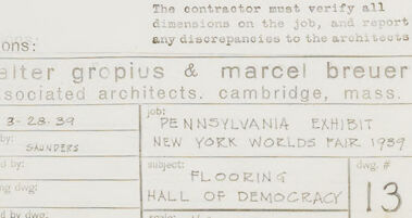
In the bottom right corner, there's a title block with the names "Walter Gropius & Marcel Breuer," indicating they are the architects associated with the project. Additional details in the title block include the project name "Pennsylvania Exhibit" for the "New York World's Fair, 1939," the specific drawing is of the "Flooring" of the "Hall of Democracy" the sheet number is "13."
Created by gemini-2.0-flash-lite on 2025-05-25
Here's a description of the image:
The image is a technical drawing, likely an architectural blueprint or plan. It is a top-down view of a space, possibly a room or a portion of a building. The drawing is rendered in fine lines and is dominated by a grid pattern which suggests it is likely the floor plan. Several labels and annotations are present, providing information about materials, dimensions, and features.
At the bottom of the image, there is a title block containing information about the project:
- Architects: Walter Gropius & Marcel Breuer
- Project: New York World's Fair, 1939
- Section: Flooring
- Location: Hall of Democracy
- Drawing Number: 13
The drawing style and the information suggest that it is likely an historical architectural drawing.
Text analysis
Amazon