Machine Generated Data
Tags
Color Analysis
Categories
Imagga
| text visuals | 99.8% | |
| paintings art | 0.2% | |
Captions
Microsoft
created on 2018-03-22
| a close up of text on a whiteboard | 78.4% | |
| a close up of a whiteboard | 78.3% | |
| a whiteboard with writing on them | 78% | |
OpenAI GPT
Created by gpt-4o-2024-05-13 on 2025-03-07
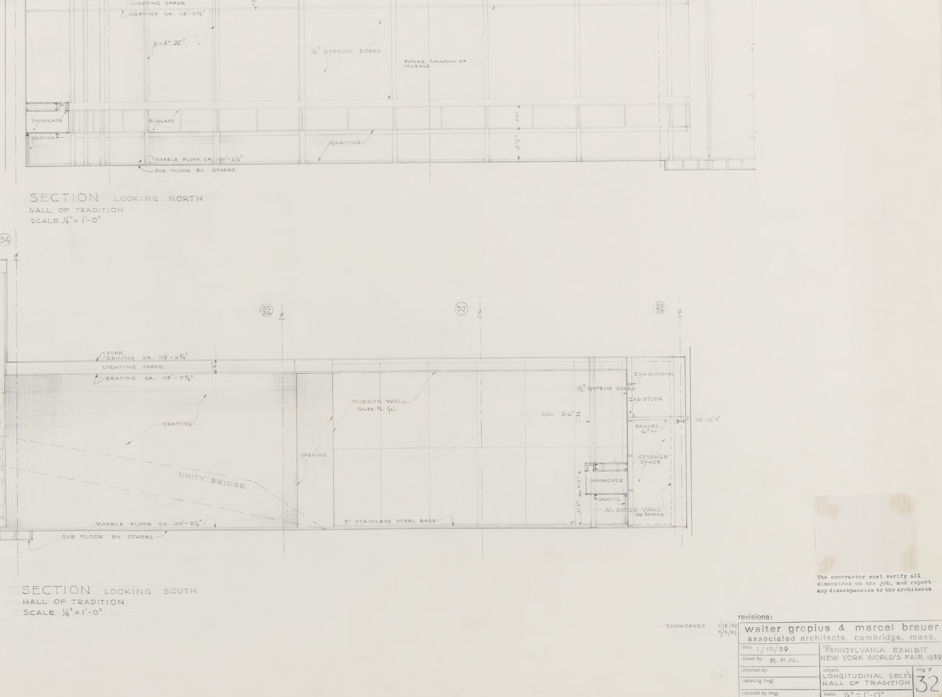
The image depicts a detailed architectural drawing, specifically sections of a building. This drawing shows two separate sectional views labeled "SECTION LOOKING NORTH - HALL OF TRADITION" and "SECTION LOOKING SOUTH - HALL OF TRADITION." It is scaled at 3/4 inches equal to 1 foot. Key elements are labeled, such as partitions, walls, benches, storage, stainless steel bars, columns, marble floors, and the "UNITY BRIDGE." The drawing includes various dimensions and annotations providing detailed measurements and notes. The title block in the bottom right corner contains information about the architects, Walter Gropius and Marcel Breuer, and their associated office in Cambridge, Massachusetts. It includes details like the drawing identification number (DRAWING NO. 32), date (9/20/55), revision dates, and the project's name, which is the "PENNSYLVANIA EXHIBITS." Overall, it is a precise and technical representation of the architectural sections of a specific hall within the larger project.
Created by gpt-4 on 2025-03-07
The image depicts architectural drawings consisting of two cross-sectional views, labeled "SECTION LOOKING NORTH" and "SECTION LOOKING SOUTH." These sections are scaled at 1/4 inch per 1 foot, indicating a detailed representation of a specific segment of a building. The drawings are technical and precise, with annotations and measurements provided for various structural elements and spaces within the building. Notable features in the drawings include labeled walls, columns, and stairs, among others. The details suggest that these sections are part of a larger set of architectural plans, intended for use in the construction or analysis of this particular structure. At the bottom right, there is metadata about the architects and project information. It includes the names "Walter Gropius & Marcel Breuer" which reference prominent figures in architecture, perhaps indicating that this is historically significant or part of their body of work. Overall, these drawings are typical documents used by architects and engineers during the planning and construction phases of a building project.
Anthropic Claude
Created by claude-3-haiku-20240307 on 2024-12-29
The image appears to be a technical drawing or architectural plan. It shows a sectional view of a structure, with detailed measurements and annotations. The drawing is labeled "Section Looking North" and "Section Looking South", indicating it is depicting multiple views or cross-sections of the same structure. The overall style and format suggest this is a professional design or engineering document, likely related to a construction or architectural project.
Created by claude-3-opus-20240229 on 2024-12-29
The image shows an architectural drawing or blueprint of what appears to be a section, ground floor plan and elevation view of a building, likely the south section of a sports hall or gymnasium based on the text at the bottom. The drawing includes dimensions and detailed markings typical of architectural plans. The image is in black and white on an aged or yellowed paper background.
Created by claude-3-5-sonnet-20241022 on 2024-12-29
This is an architectural drawing showing two sectional views of a "Wall of Tradition" - one looking north and one looking south. The drawing appears to be a professional architectural blueprint with scale measurements and technical details. The sections show various architectural elements including what appears to be display cases or exhibition spaces. The drawing is labeled with measurements and includes the architects' information - Walter Gropius & Marcel Breuer - in the title block at the bottom right corner. The scale indicated is 1/4"=1'-0". The drawing appears to be part of a larger set of architectural plans, marked as sheet 32. The lines are clean and precise, typical of professional architectural drafting of the period.
Meta Llama
Created by us.meta.llama3-2-11b-instruct-v1:0 on 2025-03-14
The image presents a technical drawing of two sections of a building, likely a house or a room, with detailed floor plans and architectural features. * **Section Looking North** * The top section is labeled "SECTION LOOKING NORTH" and features a floor plan with various rooms and spaces. * The rooms are labeled with numbers, and there are notes and annotations throughout the drawing. * The drawing includes measurements and scales, indicating the size and proportions of the rooms and spaces. * **Section Looking South** * The bottom section is labeled "SECTION LOOKING SOUTH" and features another floor plan with different rooms and spaces. * Similar to the top section, this drawing also includes measurements and scales, as well as notes and annotations. * The rooms and spaces in this section appear to be similar in size and layout to those in the top section. * **Technical Details** * The drawing includes technical details such as door and window locations, as well as the placement of furniture and other fixtures. * There are also notes about the materials used in the construction of the building, including the type of wood and the size of the beams. * The drawing appears to be a detailed and accurate representation of the building's design and layout. Overall, the image provides a comprehensive view of the building's design and layout, including its various rooms and spaces, as well as its technical details.
Created by us.meta.llama3-2-90b-instruct-v1:0 on 2025-03-14
This image depicts a technical drawing of a building's floor plan, likely created by an architect or designer. The drawing is divided into two sections, each representing a different part of the building. The top section is labeled "SECTION LOOKING NORTH" and the bottom section is labeled "SECTION LOOKING SOUTH." Both sections feature a grid pattern with various lines and symbols indicating different features such as walls, doors, windows, and other architectural elements. The drawing also includes several notes and labels throughout, providing additional information about the design and layout of the building. In the bottom-right corner, there is a small block of text that appears to be a title or description of the drawing, but it is too small to read clearly. Overall, this image provides a detailed and technical representation of a building's floor plan, showcasing the careful planning and attention to detail that goes into designing a structure.
Amazon Nova
Created by amazon.nova-lite-v1:0 on 2025-01-11
The image is a detailed architectural drawing, specifically a section view of a building. The drawing is labeled "SECTION LOOKING NORTH" and "SECTION LOOKING SOUTH" at the top, indicating that it shows two different sectional views of the same building. The scale is 1/4" = 1'-0", suggesting that the drawing is a scaled representation of the building's structure. The drawing includes various measurements and annotations, such as "HALL OF TRADE," "HALL OF TRADITION," and "SCALING 1/4" = 1'-0'." The drawing also includes a signature line at the bottom, indicating that it was created by an architect or architectural firm. The drawing appears to be a technical document used in the design and construction of the building.
Created by amazon.nova-pro-v1:0 on 2025-01-11
The image is a detailed architectural drawing of a section of a building, specifically the Hall of Tradition. The drawing is in black and white and is divided into two main sections labeled "SECTION LOOKING NORTH" and "SECTION LOOKING SOUTH." Each section is further divided into smaller sections, each representing different parts of the building's structure. The drawing includes measurements, annotations, and a scale at the bottom, indicating that it is a precise and technical representation of the building's design. The annotations include details about the building's features, such as walls, floors, and structural elements. The drawing also includes a legend or key at the bottom right corner, which provides additional information about the symbols and notations used in the drawing. Overall, the image is a professional and detailed architectural drawing that would be used by architects, engineers, and construction professionals to plan and build the Hall of Tradition.
Text analysis
Amazon