Machine Generated Data
Tags
Color Analysis
Categories
Imagga
| text visuals | 85.3% | |
| nature landscape | 7.7% | |
| events parties | 5.3% | |
| beaches seaside | 1% | |
| cars vehicles | 0.2% | |
| streetview architecture | 0.2% | |
| sunrises sunsets | 0.2% | |
Captions
Microsoft
created on 2018-03-22
| a close up of a blue wall | 42.9% | |
| a close up of a tennis court | 10.8% | |
| a close up of some water | 10.7% | |
OpenAI GPT
Created by gpt-4 on 2024-12-16
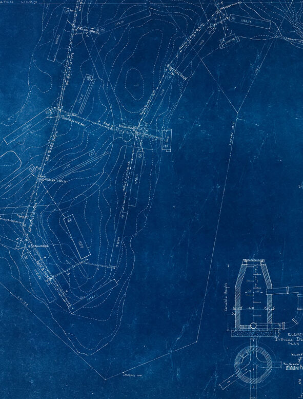
The image before you is a blueprint, characterized by its blue background with white lines and text. This particular blueprint appears to be a site plan, showing a detailed layout of a piece of land or a property from a top-down perspective. The blueprint outlines various features such as property lines, contour lines (indicating the slopes and elevations of the land), roads, manholes, sewer lines, and possibly water or gas lines, as evidenced by the symbols key present in the image. The symbols key lists out markers for common elements found in civil engineering plans, such as storm sewers, sanitary sewers, and water mains. On the bottom right corner, there is a detailed drawing which may represent some type of structure related to utilities, such as a section through a manhole or an elevation of utility-related hardware. Overall, this image is a common type of visual documentation used in civil engineering, landscaping, and urban planning to convey technical information about a specific site.
Created by gpt-4o-2024-05-13 on 2024-12-16
This image is a blueprint, which is a detailed architectural drawing. The blueprint is printed in white lines on a blue background and contains various technical details: 1. **Topography and Layout:** The central area of the blueprint consists of lines and curves which represent the topography and layout of a site. Elevations or contours indicate the rise and fall of the land. 2. **Structures and Roads:** There are several outlined shapes and annotations that likely represent structures, pathways, or roads. Various connected lines imply pathways or utilities. 3. **Cross-Section Detail:** At the bottom right corner, there are detailed diagrams of a structure, labeled "Typical Drop Manhole Drain," with dimensions and labels for various parts of the manhole. 4. **Symbols Key:** Adjacent to the cross-sectional diagram, there is a key of symbols used in the blueprint. It includes interpretations for property lines, sewer lines, water lines, fire hydrants, ground elevations, easements, retaining walls, paved ditches, utility poles, and building corners. 5. **Annotations and Measurements:** Various sections of the blueprint include annotations, measurements, and labels in small text, which provide further specifications about the infrastructure and site features. 6. **Compass/Orientation Guide:** Near the center-right edge, there is a simple compass or orientation guide that helps in understanding the orientation of the map. Overall, the blueprint provides a comprehensive technical plan for construction or civil engineering work related to the outlined area.
Anthropic Claude
Created by claude-3-haiku-20240307 on 2024-12-16
This image appears to be a blueprint or engineering diagram. It shows a detailed topographic map or layout with various symbols, lines, and measurements indicating different structures, roads, and other geographic features. The image has a distinct blue-tinted color scheme characteristic of traditional blueprint designs. It seems to be an architectural or engineering plan for a specific location or project, though the precise details are not easily discernible from this image alone.
Created by claude-3-5-sonnet-20241022 on 2024-12-16
This appears to be a vintage blueprint or technical drawing, rendered in the characteristic white lines on blue background (cyanotype) style. The image shows what appears to be a site plan or survey map on the left side, with topographical contour lines and property boundaries marked. On the bottom right, there are detailed technical drawings of what appears to be a manhole or utility access point, including an elevation view and cross-section details. There's also a legend or symbol key on the right side of the drawing that explains the various line types and markings used in the plan. The drawing has a professional, engineering quality to it and likely dates from a time when such documents were hand-drawn rather than computer-generated.
Meta Llama
Created by us.meta.llama3-2-11b-instruct-v1:0 on 2024-12-16
The image is a blueprint of a landscape design, featuring a map of the area with various features and symbols. The blueprint is drawn in white on a blue background, with a grid pattern and lines indicating the boundaries of different areas. * **Map of the Area** * The map shows a large, irregularly shaped area with several smaller areas within it. * The map includes roads, buildings, and other features, such as a pond and a park. * There are also several symbols and markings on the map, including arrows, circles, and rectangles. * **Symbols and Markings** * The symbols and markings on the map appear to be related to the design and layout of the landscape. * Some of the symbols may represent specific features or elements, such as trees, flowers, or other plants. * Others may indicate the location of utilities, such as water or electricity lines. * **Grid Pattern** * The grid pattern on the map is likely used to help measure and scale the design. * It may also be used to identify specific locations or features on the map. * **Blue Background** * The blue background of the blueprint gives it a distinctive look and feel. * It may also help to make the white lines and symbols stand out more clearly. Overall, the blueprint appears to be a detailed and well-designed plan for a landscape project. It includes a range of features and symbols that suggest a thoughtful and intentional approach to the design.
Created by us.meta.llama3-2-90b-instruct-v1:0 on 2024-12-16
The image depicts a blue map with white lines and symbols, likely representing a property or land survey. The map features various symbols and markings, including lines, shapes, and text, which appear to indicate different features such as roads, buildings, and boundaries. The overall design and layout of the map suggest that it is a technical drawing or blueprint, possibly created for planning or construction purposes.
Amazon Nova
Created by amazon.nova-lite-v1:0 on 2025-02-28
The image shows a blueprint of a property, featuring a detailed map of the land and various annotations. The map is primarily blue, with white lines delineating property boundaries, roads, and other features. The blueprint includes a legend at the bottom right, explaining the symbols used in the map. The map shows a large plot of land with multiple sections, including a residential area, a garden, and a parking lot. The blueprint also includes detailed measurements and notes, indicating the dimensions and locations of various structures and features on the property.
Created by amazon.nova-pro-v1:0 on 2025-02-28
The image is a blueprint of a land plan, drawn on a blue-colored paper with white lines. The plan includes various symbols and labels that indicate different elements of the land, such as roads, buildings, and other structures. The symbols are labeled with their respective names, such as "Property Line," "Sewer Line," "Water Line," and "Gas Line." The plan also includes a legend that explains the meaning of each symbol. The image is a detailed and precise representation of the land plan, which can be used for construction or development purposes.
Text analysis
Amazon