Machine Generated Data
Tags
Color Analysis
Feature analysis
Amazon
Clarifai

Clarifai
| Picture frame | 99.4% | |
Categories
Imagga
created on 2020-04-27
| text visuals | 100% | |
Captions
Microsoft
created by unknown on 2020-04-27
| a white sign with black text | 70.7% | |
| a black and silver text on a white surface | 67.4% | |
| a black sign with white text | 63.7% | |
Clarifai
No captions written
Salesforce
Created by general-english-image-caption-blip on 2025-05-20
a photograph of a drawing of a drawing of a plan for a staircase
Created by general-english-image-caption-blip-2 on 2025-06-29
a drawing of a building with a plan and measurements
OpenAI GPT
Created by gpt-4 on 2025-03-06
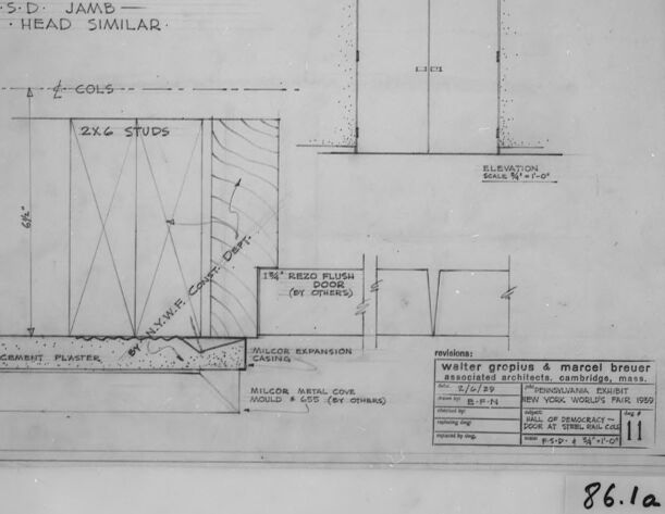
The image presents a framed architectural drawing or blueprint. There are several sections to this drawing:
On the left side, a detailed cross-sectional view of a wall, with annotations such as "F.S.D. Jamb" and "Head similar". It also shows construction details such as "2x6 Studs", "Concrete Plaster", and various molding profiles (e.g., "MILCOR CASING", "MILCOR BASE", "MILCOR ASTR. COVE").
On the right, there is an elevation view, which appears to be a door, labeled with "ELEVATION SCALE 1/2" = 1'-0".
In the lower right corner, there are "Revisions", noting the architects Walter Gropius & Marcel Breuer, associated with addresses in Cambridge, Massachusetts, and New York City. It's dated "8-7-39" indicating perhaps when the revisions were made.
The blueprint is captioned in the bottom right as "86.1a", which might refer to a catalog or inventory number.
The blueprint is monochromatic, featuring just black lines and text on a white background, as is typical for such documents.
This blueprint is indicative of the careful planning and detail that goes into the construction of architectural elements. The architects mentioned, Walter Gropius and Marcel Breuer, are notable figures in modern architecture.
Created by gpt-4o-2024-05-13 on 2025-03-06
The image is a black and white architectural drawing detailing the construction of a door jamb. The drawing includes various technical elements and measurements related to door construction and installation. Specifically, it features sections of wall studs (2x6) and other structural components like crambent plaster, metal cove molding, milcor expansion casing, and resilient channel. The elevation of the door is shown from the front, with a labeled door frame noting it as an "Rizo Flush Doors."
There are precise measurements detailing the spacing and placement of various components, such as the studs and plaster work. Engraved within the drawing is the label "F.S:D JAMB - HEAD SIMILAR," indicating that this detail applies to both the jamb and the head components of the door frame.
There is additional text in a box in the lower right corner that credits the architects: Walter Gropius & Marcel Breuer (Associated Architects, Cambridge, Mass), and the drawing's purpose is specified for an exhibit at the New York World's Fair 1939.
The drawing also includes a revision note and a label in the bottom right corner, marked "86.12a."
Anthropic Claude
Created by us.anthropic.claude-3-5-sonnet-20241022-v2:0 on 2025-06-25
This image appears to be an architectural drawing or technical blueprint. It shows construction details for what seems to be a door or wall assembly. The drawing includes specifications for "2x6 studs" and various other construction elements. There's an elevation view in the upper right corner showing what appears to be a door. The drawing has technical notations and measurements, and includes details about materials like "cement plaster" and "Milcor metal cove." The document appears to be from an architectural firm "Walter Gropius & Marcel Breuer" in Cambridge, Massachusetts. The drawing is labeled with a number "86.1a" and appears to be a professional architectural specification document.
Created by claude-3-5-sonnet-20241022 on 2025-01-14
This is an architectural drawing or blueprint detail showing construction specifications. The drawing appears to be for a door jamb or similar architectural element, with detailed measurements and material specifications. It includes both a side elevation view and a front elevation view of what appears to be a doorway. The drawing specifies "2x6 studs" and shows various construction details including cement plaster and Milcor metal cove. The drawing is labeled as being by Walter Gropius & Marcel Breuer, architects from Cambridge, Massachusetts, and appears to be from 1955. The image is in black and white and appears to be a historical architectural document with precise technical specifications and measurements.
Created by claude-3-opus-20240229 on 2025-01-14
The image shows an architectural blueprint or technical drawing titled "R.S.D. Jamb - Head Similar". It depicts a cross-section view of what appears to be part of a window or door frame, with dimensions and annotations indicating materials like plaster, cement, and metal. The drawing includes an elevation view showing further details. In the bottom right corner, there is a title block with additional information about the project, but the text is too small to read clearly in this image. The drawing is rendered in black ink or graphite on white paper and is presented in a black frame.
Created by claude-3-haiku-20240307 on 2025-01-14
The image shows a technical drawing or blueprint for a lamp head similar. It includes detailed measurements, specifications, and labels such as "R-G-Dr - JAMB HEAD SIMILAR", "2X6 STUDS", and "CEILING PLASTER". The drawing appears to be part of an architectural or engineering plan, with notes and specifications provided for various components. There are no human faces or identities visible in this image.
Meta Llama
Created by us.meta.llama3-2-90b-instruct-v1:0 on 2025-01-14
The image depicts a technical drawing of a wall section, likely for an architectural or construction project. The drawing is presented in black and white, with a white background and a black border around the edges.
Key Features:
- Wall Section: The drawing shows a detailed cross-section of a wall, including the foundation, walls, and roof.
- Labels and Annotations: Various labels and annotations are scattered throughout the drawing, providing information about the materials, dimensions, and construction methods used.
- Scale: A scale is included in the bottom-right corner of the drawing, indicating that the drawing is to scale.
- Revision Information: A revision history is listed in the bottom-right corner, showing the date and version number of the drawing.
- Stamp: A stamp or watermark is visible in the top-left corner, bearing the name "Walter Gropius & Marcel Breuer" and the location "Cambridge, Mass."
- Date: The date "5/6/59" is written in the bottom-right corner, suggesting that the drawing was created on May 6, 1959.
Overall Impression:
The drawing appears to be a detailed and accurate representation of a wall section, likely created for a specific construction project. The inclusion of labels, annotations, and a scale suggests that the drawing was intended for use by architects, engineers, or contractors. The revision history and stamp provide additional context about the drawing's creation and ownership.
Created by us.meta.llama3-2-11b-instruct-v1:0 on 2025-01-14
The image is a technical drawing of a building's head similar, specifically the area where the roof meets the wall. The drawing is labeled "F.S.D. JAMB - HEAD SIMILAR" and includes various measurements and details such as the location of studs, insulation, and other materials.
- Labeling and Measurements
- The drawing is labeled "F.S.D. JAMB - HEAD SIMILAR" in the top-left corner.
- The measurements are provided in inches and feet, with some measurements marked as "COLS" (columns).
- The drawing includes various symbols and abbreviations, such as "2x6 STUDS" and "1 1/2 REZO PLUSH DOOR (BY OTHERS)".
- Materials and Details
- The drawing shows the location of various materials, including studs, insulation, and cement plaster.
- The drawing also includes details about the door, such as the type of door and the location of the hinges.
- Overall Structure
- The drawing provides a detailed view of the head similar area, including the roof, walls, and door.
- The drawing appears to be a technical drawing created for construction or architectural purposes.
In summary, the image is a technical drawing of a building's head similar, providing detailed measurements and information about the materials and construction of the area. The drawing includes various symbols and abbreviations, and provides a clear view of the overall structure of the head similar area.
Amazon Nova
Created by amazon.nova-pro-v1:0 on 2025-01-14
The image is a black-and-white architectural blueprint or drawing, framed within a black border. The drawing is divided into several sections, each labeled with specific details. The top section reads "F.S.D. JAMB - HEAD SIMILAR," indicating a similar design for the jamb and head of a door or window. Below this, there is a section labeled "2X6 STUDS," which refers to the size of the wooden studs used in construction.
Further down, there is a note about "13/4" REZO PLUSH DOOR (BY OTHERS)," indicating the type of door material and its supplier. Another section mentions "CEMENT PLASTER" and "MILCOR EXPANSION CASING," suggesting materials used for the wall and casing. The bottom section of the drawing includes a revision note, "Walter Gropius & Marcel Breuer associated architects. Cambridge, Mass. 2/6/29," indicating the architects involved and the date of the revision.
Additionally, there is a note about "MILCOR METAL COVE MOULD 4 655 (or OTHERS)," specifying the type of molding used. The drawing also includes a reference to "86.1a," possibly a page number or section identifier within a larger document. The blueprint provides detailed dimensions and specifications for the construction elements, essential for builders and contractors to follow the design accurately.
Created by amazon.nova-lite-v1:0 on 2025-01-14
The image is a technical drawing or blueprint, likely from an architectural or engineering context. The drawing shows a detailed plan of a structure, possibly a building or a part of a building. The drawing includes various labels and dimensions, indicating specific measurements and materials. The drawing is divided into sections, each labeled with different components and materials, such as "F.S.D. JAMB HEAD SIMILAR," "2X6 STUDS," "13% REZO FLUSH DOOR," and "MILCOR EXPANSION CASING." The drawing also includes a table with dimensions and materials, such as "CEMENT PLASTER," "MILCOR METAL COVE MOLD," and "B-M-R." The drawing is labeled "86.1a," indicating it is part of a larger set of drawings or plans. The drawing appears to be a detailed and technical representation of a structure, intended for use by architects, engineers, or construction professionals.
Created by amazon.nova-pro-v1:0 on 2025-01-12
The image shows a blueprint of a building. The blueprint has a black border and is divided into sections with labels and measurements. The top section has a label that reads "F.S.D. JAMB HEAD SIMILAR," while the bottom section has a label that reads "REVISIONS." The blueprint also includes a table with columns labeled "DATE," "REVISIONS," "ASSOCIATED ARCHITECT," "CAMBRIDGE, MASS.," "PENNSYLVANIA EXHIBIT," and "NEW YORK WORLD'S FAIR 1950." The table has entries for dates, revisions, and associated architects. The blueprint also includes a number "86.1a" in the bottom right corner.
Created by amazon.nova-lite-v1:0 on 2025-01-12
The image appears to be a technical drawing or blueprint of a structure, possibly a door or window jamb. The drawing is labeled "F:S.D. JAMB HEAD SIMILAR" and includes various dimensions and specifications.
The drawing shows a cross-section of the jamb, with labels indicating the type of material used (e.g., "CEMENT PLASTER") and the size of the studs (e.g., "2X6 STUDS"). The drawing also includes information about the elevation, which is likely the height of the structure.
The drawing is signed by "Walter Gropius & Marcel Breuer," who were renowned architects associated with the Bauhaus movement. The drawing is dated "2/6/29," which suggests that it may have been created in the late 1920s.
The image also includes a table with additional information about the structure, including the type of door ("MILCOR METAL COVE MOLD") and the size of the door ("4.55" x 6.55"). The table also includes a reference to the "New York World's Fair 1950," which suggests that the structure may have been part of an exhibit or display at the fair.
Overall, the image appears to be a technical drawing of a door or window jamb, created by renowned architects Walter Gropius and Marcel Breuer in the late 1920s. The drawing includes various dimensions and specifications, as well as a reference to the New York World's Fair 1950.
Google Gemini
Created by gemini-2.0-flash on 2025-04-29
Here is a description of the image:
The image shows a black and white architectural drawing framed in black. The drawing consists of multiple sketches or diagrams with labels and dimensions, suggesting it's a technical plan or elevation view.
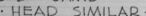
In the upper left quadrant, text reads "FSD JAMB - HEAD SIMILAR", with an element labeled "COLS" below it. Adjacent is a drawing of "2x6 STUDS" and the label "NYWF CONST. DEPT."
The middle section features a drawing labeled "1 3/4" REZO FLUSH DOOR (BY OTHERS)", with additional elements labeled "MILCOR EXPANSION CASING" and "MILCOR METAL COVE MOULD # 655 (BY OTHERS)."
In the upper right quadrant, an "ELEVATION" is drawn with a scale indicated as "3/4 = 1-0".
Below the drawings, there is text containing revisions, architects' names ("walter gropius & marcel breuer"), and details about the project ("PENNSYLVANIA EXHIBIT NEW YORK WORLD'S FAIR 1950"). A drawing sheet reference is indicated as "F-S-D-34 1-0"
Finally, the number "86.1a" is visible in the bottom right corner.
Created by gemini-2.0-flash-lite on 2025-04-29
Here's a description of the image:
Overall:
The image is a detailed architectural drawing, likely an elevation and cross-section view. It's framed in a black border and appears to be a photograph of a blueprint or a similar technical illustration.
Content & Features:
- Architectural Detail: The drawing appears to depict a door frame and surrounding wall construction, showing elements like studs, plaster, casing, and a "Rezo Flush Door".
- Annotations: There are numerous handwritten annotations, labels, and measurements throughout the drawing. These details are crucial for the construction or design process.
- Text and Labels: Clearly labeled notes include phrases like "F.S.D. JAMB-HEAD SIMILAR" and "2X6 STUDS".
- Dimensions and Scale: The scale "3/4" - 1'-0" is indicated, showing the precise ratio used in the drawing.
- Information Block: The lower right corner includes a block with the architect's name ("Walter Gropius & Marcel Breuer"), project name ("Pennsylvania Exhibit, New York World's Fair, 1939"), and other details.
- Revisions: There's a "revisions" section.
- "86.1a" Label: The bottom right has the label "86.1a".
Style & Tone:
- Technical: The image has a very technical and precise aesthetic. It is clearly designed for communication within the architecture or construction fields.
- Historical: This drawing comes from 1939, giving a glimpse of how architecture was documented and communicated during that period.
In essence, the image is a well-preserved technical drawing of a door frame and its surrounding structure. It provides valuable information about the architectural style, the construction techniques, and the designers involved in this project.
Mistral Pixtral
Created by us.mistral.pixtral-large-2502-v1:0 on 2025-05-27
The image is a detailed architectural drawing, specifically a sectional elevation, for a construction project. Here are the key elements and details noted in the drawing:
Title and Identification:
- The drawing is titled "F.S.D. JAMB - HEAD SIMILAR".
- There is a reference number "86.1a" at the bottom right corner.
Dimensions and Layout:
- The drawing shows a vertical section of a wall with specific measurements.
- The wall height is indicated as "ELEVATION 102'-0".
- The width of the section is labeled "4'-0 COLS" (columns).
Materials and Components:
- The wall consists of 2x6 studs.
- There is a 1/8" KEZO flush door (plywood) included in the section.
- The drawing shows cement plaster on the exterior side.
- There is an aluminum expansion casing and a Milcor metal cover frame and cap.
Annotations:
- Various annotations are present, such as "ALUM.F. CASE & CAP" and "MILCOR METAL COV. FRAME & CAP".
- There are notes indicating the materials and specifications, such as the type of door and casing.
Revisions:
- The drawing includes a revision note indicating changes made by "WALTER GROPIUS & MARCEL BREUER ASSOCIATED ARCHITECTS, CAMBRIDGE, MASS."
- The revision date is noted as "5/6/59".
Additional Information:
- The drawing is framed, suggesting it might be part of a display or archive.
- There are some handwritten notes and stamps, indicating it has been reviewed or approved.
This drawing appears to be a detailed sectional view of a wall assembly, likely for a specific architectural project, with precise measurements and material specifications.
Qwen
Created by Qwen/Qwen2.5-VL-7B-Instruct on 2025-07-26
This image appears to be an architectural drawing, specifically a section or elevation view, detailing the construction of a door frame and its surrounding structure. The drawing includes labeled dimensions and materials used. Here’s a breakdown of the details:
Title and Description:
- The top left of the drawing mentions "F.S.D. JAMB HEAD SIMILAR," which likely refers to the frame and head of the door.
- Below this, the drawing specifies "2X6 STUDS" indicating the use of 2x6 lumber for the framing.
Dimensions:
- There is a scale at the top right of the drawing which indicates "ELEVATION SCALE 1/4" = 1'-0"". This is used to convert the distances in the drawing to full-size dimensions.
- The drawing shows a height of "61/2" for the frame, and the width of the door opening is "1' 0" (12 inches).
Materials and Construction Details:
- The bottom of the drawing shows the foundation and the materials used:
- "CEMENT PLASTER" for the base layer.
- "MILCOR METAL COVE MOULD & GGS" (by others) suggesting the use of metal cove molding and possibly gypsum products.
- The center of the drawing shows a door and its frame with labels like "1% REZO FLUSH DOOR (BY OTHERS)" indicating a flush door made by another manufacturer.
- "MILCOR EXPANSION CASING" is also noted, possibly referring to an expansion joint material.
- "STKYWWF COURT DEPT." likely refers to a court department or a specific detail related to the construction.
- The bottom of the drawing shows the foundation and the materials used:
Architectural Details:
- The drawing includes sectional lines and arrows indicating the depth and length of the frame and the relationship between the door and its surroundings.
- There is a note about "2 COLS" indicating the presence of two columns or supports in the foundation.
Revisions and Credits:
- In the bottom right corner, there is a note for "WALTER GROPIUS & MARCEL BREUER associated architects, cambridge, mass." This indicates the architects involved in the project.
- The drawing also includes credits and references to a "Pennsylvania Exhibit" and "New York World's Fair 1939-40," suggesting that this drawing is related to a design project for an exhibit at the 1939-1940 New York World's Fair.
This drawing is a detailed architectural specification that provides尺寸和材料信息 for the construction of a door frame and its surroundings, possibly for an exhibit at a significant fair.
Created by Qwen/Qwen2.5-VL-72B-Instruct on 2025-07-26
This image is a black-and-white architectural drawing or blueprint detailing the construction of a door frame and jamb, labeled "F.S.D. JAMB - HEAD SIMILAR." The drawing includes both an elevation view and a cross-sectional view.
Key Components:
Elevation View:
- Depicts a door frame and door, with dimensions and details.
- The scale of the elevation is indicated as 1/4" = 1'-0".
Cross-Sectional View:
- Shows the framing structure, including:
- 2x6 Studs: Supporting the frame.
- Rezo Flush Door: The door itself, noted as being supplied by others.
- Cement Plaster and Milcor Expansion Joint: Materials for the finish and to prevent cracking.
- Milcor Metal Cove Mould & GSS: Additional finishing components.
- Shows the framing structure, including:
Text and Annotations:
- Various labels and notes describe materials and construction details.
- The drawing is credited to "Walter Gropius & Marcel Breuer, associated architects, Cambridge, Mass."
- It is associated with the "Pennsylvania Exhibit, New York World’s Fair 1939."
Date and Revisions:
- A revision date of 5/2/39 is noted.
Additional Markings:
- A handwritten notation "86.1a" appears in the bottom right corner.
The document appears to be a professionally prepared architectural plan for a specific project related to a World's Fair exhibit.
Text analysis
Amazon