Machine Generated Data
Tags
Color Analysis
Feature analysis
Amazon

| Airplane | 65% | |

Categories
Imagga
| text visuals | 99% | |
| paintings art | 0.9% | |
| food drinks | 0.1% | |
Captions
Microsoft
created on 2018-03-22
| a close up of text on a whiteboard | 72.5% | |
| a close up of a whiteboard | 72.4% | |
| a whiteboard with writing on them | 71.4% | |
OpenAI GPT
Created by gpt-4 on 2025-03-08
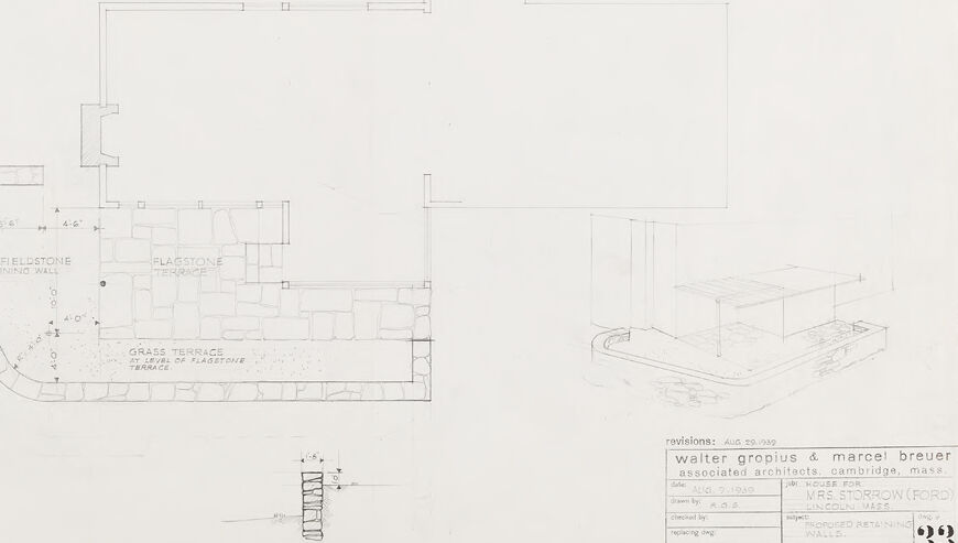
This image appears to be an architectural drawing or blueprint. The drawing includes a plan view of a building or section of a building, showing the layout of walls and some design elements such as terraces. On the lower portion of the drawing, there appears to be a small isometric view of what might be a section of the building, showing a three-dimensional perspective. There are annotations and labels throughout, denoting features like a "DRY FIELDSTONE RETAINING WALL" and a "FLAGSTONE TERRACE." The plan also includes scaled measurements, and there is a title block in the lower right corner revealing the design is connected to architects "Walter Gropius & Marcel Breuer, Associated Architects, Cambridge, Mass." It also indicates the project name or client as "W.J. RUSSE FOR D." and a location in Lincoln, Mass. This drawing seems to be related to mid-century modern architecture, considering the associated architects.
Created by gpt-4o-2024-05-13 on 2025-03-08
The image is a black and white architectural drawing. It includes a detailed plan of a house and patio area. The drawing shows a "Flagstone Terrace" and "Dry Fieldstone Retaining Wall" located adjacent to the house. There is also a mixture of "Grass Terrace" and flagstone, indicating a landscaped outdoor space. On the bottom right corner, there is a smaller, isometric view of the house and the terrace area, providing a 3D perspective. The lower right part of the drawing includes text that identifies the architects and the project details. This includes the names "Walter Gropius & Marcel Breuer," who are noted as associated architects from Cambridge, Massachusetts. The project was prepared for "Mrs. Storrow (Ford)" in Lincoln, Mass. The drawing is labeled with the title "House for Mrs. Storrow (Ford), Lincoln Mass" and mentions "Encroached Retaining Walls." There are also references to a revision, which is dated August 30, 1939. The plan is detailed with measurements and notes indicating various elements of the design, such as dimension lines and specific architectural features. The detailed labeling serves to communicate the functional and aesthetic elements of the design for construction or further planning.
Anthropic Claude
Created by claude-3-haiku-20240307 on 2024-12-31
The image appears to be an architectural blueprint or technical drawing. It shows a detailed floor plan or layout with various labeled elements, including walls, doors, and other structures. There are also some technical details and annotations visible on the drawing. The overall style and presentation suggest this is an engineering or construction-related document.
Created by claude-3-5-sonnet-20241022 on 2024-12-31
This is an architectural drawing or blueprint, specifically a floor plan that appears to be drawn by Walter Gropius & Marcel Breuer Associates Architects from Cambridge, Massachusetts. The drawing shows a detailed ground plan with what looks like a curved or semi-circular element along one edge. There are various room divisions and spatial arrangements shown in the plan. The drawing also includes some perspective sketches or details in the lower portions of the sheet. The document appears to be a revision dated August 20, 1940. It's drawn in a minimal, clean style typical of modernist architectural drawings of that era, with thin lines on what appears to be white paper or vellum.
Meta Llama
Created by us.meta.llama3-2-11b-instruct-v1:0 on 2025-03-15
The image is a technical drawing of a building's floor plan and elevation, created by Walter Gropius and Marcel Breuer, associated architects. The drawing is dated August 20, 1939. * **Floor Plan:** * The floor plan is drawn in pencil on white paper. * It shows the layout of the building, including the location of rooms, doors, windows, and other features. * The plan includes labels for different areas, such as "DRY FIELDSTONE" and "GRASS TERRACE". * There are also notes and measurements throughout the plan. * **Elevation:** * The elevation drawing shows the exterior of the building from a specific angle. * It includes details such as the shape and size of the building, the location of windows and doors, and the type of materials used in its construction. * The elevation drawing is also drawn in pencil on white paper. * **Labels and Notes:** * The drawing includes labels and notes that provide additional information about the building. * These labels and notes include the names of the architects, the date of the drawing, and other relevant details. * They also provide context for the drawing, such as the location of the building and the purpose it was designed for. * **Scale:** * The drawing includes a scale that indicates the size of the building in relation to the actual size of the paper. * The scale is marked in inches and feet, allowing the viewer to measure the building's dimensions accurately. * **Other Features:** * The drawing includes other features that provide additional information about the building. * These features include arrows and lines that indicate the direction of doors and windows, as well as symbols that represent different types of materials used in the building's construction. Overall, the image is a detailed and informative technical drawing that provides a comprehensive view of the building's design and layout. It is likely to be used by architects, engineers, and other professionals involved in the construction or renovation of the building.
Created by us.meta.llama3-2-90b-instruct-v1:0 on 2025-03-15
This image presents a technical drawing of an architectural design, likely for a building or structure. The drawing is rendered in black ink on a white background and features various elements that provide insight into the design's layout and features. **Key Elements:** * **Floor Plan:** The central focus of the drawing is a floor plan, which outlines the rooms and spaces within the building. The plan includes labels and measurements to facilitate understanding and construction. * **Elevations:** Two elevation drawings are positioned to the right of the floor plan. These drawings depict the building's exterior from different angles, providing a visual representation of its appearance. * **Section Drawing:** A section drawing is located below the floor plan. This drawing shows a cross-section of the building, offering a detailed view of its internal structure and layout. * **Labels and Measurements:** Throughout the drawing, labels and measurements are used to identify specific features and dimensions. These annotations help to clarify the design and ensure accurate construction. * **Architectural Details:** The drawing includes various architectural details, such as doors, windows, and columns. These elements contribute to the overall aesthetic and functional design of the building. **Overall Impression:** The technical drawing presents a comprehensive and detailed design for a building or structure. The inclusion of multiple views, labels, and measurements demonstrates a thorough understanding of the design principles and construction requirements. The drawing serves as a valuable tool for architects, engineers, and builders to bring the design to life.
Amazon Nova
Created by amazon.nova-lite-v1:0 on 2025-01-13
The image shows a floor plan of a house designed by Walter Gropius and Marcel Breuer. The plan includes a rectangular building with a central open space and several rooms surrounding it. The central space appears to be a courtyard or atrium, with a staircase leading to the upper level. The surrounding rooms include a living room, dining room, kitchen, and bedrooms. The floor plan also includes details such as the location of windows, doors, and other architectural features. The image appears to be a draft or sketch, as it includes notes and revisions in the bottom right corner.
Created by amazon.nova-pro-v1:0 on 2025-01-13
The image is a black-and-white architectural plan of a building. The plan is divided into several sections, including a central rectangular area labeled "FLAGSTONE TERRACE," surrounded by other labeled sections such as "DRY FIELDSTONE RETAINING WALL" and "GRASS TERRACE AT LEVEL OF FLAGSTONE TERRACE." There is a small inset drawing in the bottom right corner that appears to be a detailed section or elevation of a portion of the building. The plan includes dimensions and annotations, and it is dated August 29, 1939. The architects are identified as Walter Gropius and Marcel Breuer, associated with Architects, Cambridge, Mass. The plan is for a house for Mrs. Strowrow (Ford) Lincoln Mass.
Text analysis
Amazon