Machine Generated Data
Tags
Color Analysis
Feature analysis
Amazon

| Document | 59.5% | |
Categories
Imagga
| text visuals | 100% | |
Captions
Microsoft
created on 2018-03-22
| a close up of text on a whiteboard | 80.6% | |
| close up of text on a whiteboard | 78.1% | |
| a close up of a whiteboard | 76.2% | |
OpenAI GPT
Created by gpt-4 on 2025-03-07
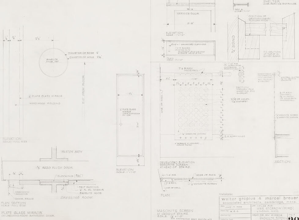
The image shows several architectural drawings and details, which appear to be part of a building or interior design plan. There are multiple views and sections, including elevations, plans, and sections of specific features. The drawings are annotated with measurements, material specifications, and notes. The drawings include design details for elements like a service door, a masonite screen at the head of stairs, and sections of a building facade. In the lower right corner, there is text indicating the designers or architects: Walter Gropius & Marcel Breuer, Associated Architects, located in Cambridge, Massachusetts. This suggests that the drawings could be part of a project handled by these well-known architects. Below the names of the architects, there are revision notes that reference a project number or code (K.6.4.), the date of July 9, a record of changes made to the drawings, including mirror and screen adjustments, and initials presumably of the person or persons who made or authorized the revisions. The architectural style and precision of the drawings suggest they could be for a modern or mid-century building, given the involvement of Gropius and Breuer, who are known for their contributions to modernist architecture. The paper appears aged, indicating that these plans may be from a historical project.
Created by gpt-4o-2024-05-13 on 2025-03-07
The image appears to be an architectural drawing or blueprint showcasing various design details for a project. It includes measurements and specifications for different components of the design. Here's a breakdown of the elements present in the drawing: 1. **Plate Glass Mirror and Hardwood Molding**: - Detailed elevation view with specific measurements (Scale: Full Size). - Mirror placement with dimensions. - Hardwood molding details around the mirror and door frame. 2. **Service Door**: - Side elevation view labeled "SERVICE DOOR." - Dimensions for the door, including pitch and position relative to groove fabric. 3. **Shelter Over Service Entrance**: - Side section view showing the shelter structure with precise measurements. - Elevation view illustrating the top view of the shelter and the arrangement of certain elements. 4. **Section Views**: - Detailed section views of various components, including screen panels and molding details. 5. **Masqonite Screen**: - Plan and elevation details for a screen ahead of stairs. - Developed elevation illustrating hole patterns and screw hole placements in masqonite material. 6. **Dressing Room and Master Bath**: - Plan section of the dressing room door, showing the placement of the plate glass mirror and surrounding structure. - Elevation view of the dressing room door from a specific height above the floor. 7. **Title Block**: - Information about the architects ("Walter Gropius & Marcel Breuer, associated architects, Cambridge, Mass") and clientele ("MRS. H. SORROW (FORD), Lincoln Mass"). - Purpose ("HOUSE FOR MRS. SORROW"). - Miscellaneous notes and revisions. Overall, this image is a technical document providing comprehensive construction and design specifics for various components within an architectural project.
Anthropic Claude
Created by claude-3-haiku-20240307 on 2024-12-31
This image appears to be an architectural drawing or blueprint. It contains detailed technical specifications, measurements, and diagrams for various elements of a building or structure, including a shelter, service door, dressing room, and masonry screen. The drawing provides an elevation view, section view, and plan view, indicating this is a comprehensive set of design plans. While the image does not contain any human faces or identifiable individuals, it provides a wealth of technical information about the structural and functional elements of the proposed construction project.
Created by claude-3-5-sonnet-20241022 on 2024-12-31
This is an architectural drawing or blueprint showing various technical details and specifications. The drawing appears to be for interior elements of a building, including: 1. A plate glass mirror detail with hardwood molding 2. A dressing room layout 3. A service door specification 4. A masonite screen design for a stairway area 5. Various elevation and section views The drawing includes precise measurements and dimensions throughout, and appears to be professionally drafted. At the bottom of the drawing, there's a title block indicating this was created by architects Walter Gropius & Marcel Breuer, located in Cambridge, Mass. The drawing is numbered "32" and includes the date July 10, 1939. It appears to be part of a larger set of architectural plans, possibly for a residential project. The details are meticulously drawn with clear annotations and specifications for construction purposes. The drawing uses standard architectural conventions and symbols to communicate design intent to builders and contractors.
Meta Llama
Created by us.meta.llama3-2-11b-instruct-v1:0 on 2025-03-13
The image presents a detailed architectural drawing of a bathroom, showcasing various elements such as the shower, bathtub, sink, and toilet. The drawing is rendered in pencil on a piece of paper, with precise measurements and labels indicating the location of each feature. * **Shower** * Located in the top-left corner of the drawing * Features a circular shower head with a diameter of 2 inches * Has a rectangular base with a width of 24 inches and a length of 36 inches * Includes a glass door with a diameter of 2 inches * **Bathtub** * Situated in the center of the drawing * Measures 60 inches in length, 30 inches in width, and 12 inches in height * Has a rectangular shape with a flat top and sloping sides * Features a faucet and drain located at the bottom * **Sink** * Positioned below the bathtub * Measures 24 inches in length, 18 inches in width, and 6 inches in height * Has a rectangular shape with a flat top and sloping sides * Features a faucet and drain located at the bottom * **Toilet** * Located in the bottom-right corner of the drawing * Measures 24 inches in length, 18 inches in width, and 6 inches in height * Has a rectangular shape with a flat top and sloping sides * Features a toilet seat and lid located at the top In summary, the image provides a detailed and accurate representation of a bathroom's layout, highlighting the various features and fixtures that are typically found in such a space. The drawing is well-organized and easy to follow, making it a useful tool for architects, designers, and builders.
Created by us.meta.llama3-2-90b-instruct-v1:0 on 2025-03-13
This image is a blueprint for a house, specifically the first floor. The blueprint is divided into two sections, with the left side showing the elevation and plan section of the plate glass mirror, dressing room, and master bath. The right side shows the elevation and plan section of the service door, masonite screen at head of stairs, and shelter over service entrance. The blueprint includes various details such as the diameter of the rose, elevation scale, and section scale. It also features a key that explains the different symbols and abbreviations used in the blueprint. The background of the blueprint is white, with black lines and text used to illustrate the design. Overall, this blueprint provides a detailed and technical representation of the first floor of a house, showcasing the layout and design of the various rooms and features.
Amazon Nova
Created by amazon.nova-lite-v1:0 on 2025-02-26
The image is a technical architectural drawing, likely from a construction or renovation project. It appears to be a floor plan and elevation details for a specific area, possibly a bathroom or a similar space. The drawing is divided into sections, with the top left section showing a circular opening, possibly a bathtub or a shower, with measurements and details such as the diameter of the rose (2' 6") and the diameter of the hole (2' 6"). The top right section depicts a service door with a scale and elevation details. The bottom section provides a plan view of the space, including dimensions, materials, and specific details such as the use of a plate glass mirror, hardwood molding, and a masonite screen. The drawing also includes notes and specifications for the contractor, such as the requirement for the contractor to supply all necessary dimensions and materials to the architect. The drawing is signed by Walter Gropius and Marcel Breuer, indicating that it is from their architectural firm.
Created by amazon.nova-pro-v1:0 on 2025-02-26
The image is a technical drawing of a bathroom, with various annotations and measurements. The drawing is divided into several sections, each labeled with specific details about the bathroom's design and construction. In the top-left corner, there is a section labeled "ELEVATION SCALE 1:10," which indicates the scale of the elevation drawing. Below this, there is a section labeled "ELEVATION," which shows the front view of the bathroom. This section includes dimensions for the walls, door, and window, as well as annotations for the materials used, such as "MASONITE SCREEN" and "HARDWOOD MOLDING." To the right of the elevation drawing, there is a section labeled "SECTION," which shows a cross-sectional view of the bathroom. This section includes dimensions for the ceiling, walls, and floor, as well as annotations for the materials used, such as "MASONITE SCREEN" and "HARDWOOD MOLDING." Below the elevation and section drawings, there is a section labeled "PLAN," which shows a top-down view of the bathroom. This section includes dimensions for the room's layout, including the location of the door, window, and fixtures, as well as annotations for the materials used, such as "MASONITE SCREEN" and "HARDWOOD MOLDING." Overall, the image provides a detailed and technical representation of a bathroom's design and construction, with specific measurements, materials, and annotations to guide the construction process.
Text analysis
Amazon