Machine Generated Data
Tags
Color Analysis
Feature analysis
Amazon
Clarifai

Clarifai
| Whiteboard | 51.5% | |
Categories
Imagga
created on 2018-03-22
| text visuals | 99.9% | |
| paintings art | 0.1% | |
Captions
Microsoft
created by unknown on 2018-03-22
| a screenshot of a computer | 55.8% | |
| a close up of text on a white surface | 55.7% | |
| a close up of a computer | 50.3% | |
Clarifai
No captions written
Salesforce
Created by general-english-image-caption-blip-2 on 2025-06-29
a drawing of a building with a plan and drawings
Created by general-english-image-caption-blip on 2025-05-03
a photograph of a drawing of a plan for a house
OpenAI GPT
Created by gpt-4 on 2025-03-05
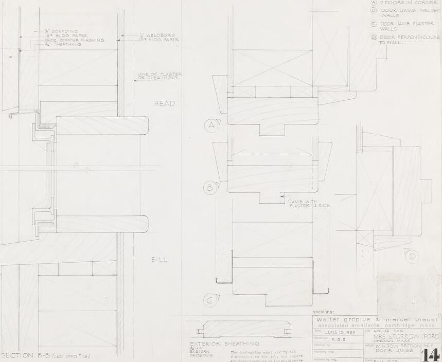
The image appears to be an architectural drawing or detail sheet with different sections and details related to construction elements of a building. On the left side of the paper, you can see a detailed section labeled "SECTION E - E" showing the composition of a window assembly, including parts called "HEAD" and "SILL." Various materials and building layers are clearly marked, such as "BOARDS," "BUILDING PAPER," "EXT. PLYWOOD SHEATHING," etc. This side of the image contains annotations indicating the dimension and materials used in the construction.
On the right side of the drawing, there are four different subsections labeled A, B, C, and D. Each provides a detail of a different aspect of a door frame installation, showing the door jambs, the walls, and how the door might be positioned in relation to the wall, whether it be in a corner, against a flat wall, or perpendicular.
At the bottom of the page, there is a footer stating the project name, location, architect, date (which seems to be "June 15, 1949"), and the scale of the drawing ("FULL SIZE"). The sheet is marked as "14" which likely indicates its sequence in a set of construction documents.
The physical condition of the paper suggests some wear and possibly aging, as evidenced by the creasing and discoloration visible in the bottom right corner. It is a technical drawing likely intended for construction or architectural use.
Created by gpt-4o-2024-05-13 on 2025-03-05
The image appears to be an architectural drawing created by Walter Gropius & Marcel Breuer, associated architects based in Cambridge, Massachusetts. It is titled "House for Mrs. Storrow (Ford) Winchester, Mass." and dated June 15, 1949. The drawing details the window section and door jamb at full size, labeled as drawing number 14.
The main elements in the drawing include:
Sections and Elevations:
- A detailed side view of a window section labeled "SECTION B-B," showing different components such as the head, sill, boarding, building paper, flashing, and sheathing.
- Other specific sections and components detail labeled A, B, C, A', B', and C' which seem to describe various conditions and interactions of walls, door jambs, plaster, and sheathing.
Materials and Notes:
- Notations mentioning materials like 2” boarding, 15 lbs. bldg paper, copper flashing, sheathing, and weldbord.
- Instructions and measurements that assist in the construction process, such as "THE CONTRACTOR MUST VERIFY ALL DIMENSIONS ON JOB, AND SATISFY HIMSELF THIS INSTALLATION CAN BE MADE AS DRAWN."
Key:
- The drawing key identifies the following details:
- A: 2 Doors in Corner
- B: Door Jamb: Weldbord Walls
- C: Door Jamb: Plaster Walls
- D: Door Perpendicular to Wall
- The drawing key identifies the following details:
Overall, the drawing provides precise instructions and measurements for constructing the window and door sections for Mrs. Storrow’s house, ensuring proper installation according to the design intentions of the architects.
Anthropic Claude
Created by claude-3-haiku-20240307 on 2024-12-29
This image appears to be a detailed architectural drawing or schematic, likely for a building or construction project. It contains various labeled components and technical details, such as measurements, materials, and structural elements. The drawing appears to be divided into different sections, with multiple views and cross-sections provided. Overall, this image seems to be a technical document intended for use in the planning and construction of a specific structure.
Created by claude-3-opus-20240229 on 2024-12-29
The image appears to be an architectural blueprint or technical drawing. It shows a cross-section view of what looks like the head and bill (beak) portion of some larger structure, based on the labels "HEAD" and "BILL" on the diagram.
The drawing contains various components labeled with letters A through F, along with notes specifying materials like "6" rock prepped/regular to wall", "dove grey canister walls", and details on items like flashing, sheathing, and anchor bolts.
At the bottom, a notes section provides a legend explaining that "Walter gropius & TAC" were the architects and engineers for the project, referencing "Cambridge, Mass" which likely indicates Massachusetts.
The structured, technical nature of the labeled cross-section suggests this is a construction or fabrication drawing, capturing details for building some portion of a larger architectural work or installation. The head and bill references imply it may be part of an animal or bird-shaped structure.
Created by claude-3-5-sonnet-20241022 on 2024-12-29
This is an architectural drawing or technical detail showing door and window construction details. The image appears to be a section drawing labeled "SECTION B-B" showing various components like exterior sheathing, headers, sills, and jamb details. The drawing includes specific callouts for construction elements like "BLOCKING" and "PLYWOOD PAPER" layers. On the right side of the drawing, there are additional details labeled A through D showing different door configurations. The drawing is a professional architectural document, dated June 15, 1949, and includes title block information at the bottom. It appears to be part of a larger set of construction documents, marked as sheet 14, and was created by Walter Gropius & Associates architects in Cambridge, Massachusetts.
Created by us.anthropic.claude-3-5-sonnet-20241022-v2:0 on 2025-06-26
This is an architectural drawing or technical blueprint showing detailed door and wall construction details. The image appears to be from 1949 and was created by Walter Gropius & Associates architects in Cambridge, Massachusetts. The drawing includes various section views labeled A through D showing door jamb, header, and wall assembly details. There are specific callouts for elements like "exterior sheathing," "head," and "sill." The main section labeled "SECTION B-B" shows construction layers including boarding, building paper, and other components. The drawing appears to be for a residential project, specifically noted as "HOUSE FOR MRS. STORROW FORD." The level of detail suggests this was meant for construction documentation, with precise measurements and assembly instructions for builders to follow.
Meta Llama
Created by us.meta.llama3-2-11b-instruct-v1:0 on 2025-03-11
The image depicts a technical drawing of a building's exterior, specifically focusing on the section of the wall where the doors are located. The drawing is labeled "SECTION B-B (see plan)" and includes various details such as the location of the doors, windows, and other architectural features.
Key Features:
- Doors: The drawing shows two doors, one on either side of the wall, with labels indicating their location and orientation.
- Windows: There are two windows visible in the drawing, one above each door.
- Wall: The wall is composed of several layers, including a plaster exterior and a wooden frame.
- Architectural Features: The drawing also includes details about the building's architectural features, such as the type of windows and doors used, and the location of any decorative elements.
Technical Details:
- Scale: The drawing is scaled at 1/4 inch = 1 foot.
- Materials: The drawing indicates that the wall is constructed using plaster and wood.
- Dimensions: The drawing provides measurements for the doors, windows, and other features, allowing for precise construction.
Overall:
The image provides a detailed and technical representation of a building's exterior, highlighting the various components that make up the wall and its features. The drawing is likely used by architects, builders, or contractors to plan and execute the construction of the building.
Created by us.meta.llama3-2-90b-instruct-v1:0 on 2025-03-11
The image presents a detailed architectural drawing of a window section, showcasing the intricate design and construction elements. The drawing is rendered in black ink on white paper, with various sections labeled and annotated to provide clarity.
Key Features:
- Window Section: The central focus of the drawing, the window section is depicted in meticulous detail, including the frame, sash, and surrounding walls.
- Labels and Annotations: Throughout the drawing, labels and annotations are used to identify specific components, such as "HEAD," "SILL," and "SECTION B-B." These labels provide context and help to clarify the design intent.
- Sectional Views: The drawing includes sectional views of the window, allowing for a deeper understanding of the construction details and how the various components interact.
- Scale and Dimensions: The drawing includes a scale and dimensions, providing a sense of proportion and size.
- Revision Information: In the bottom-right corner, revision information is noted, indicating that the drawing was revised by Walter Gropius & Marcel Breuer, Associated Architects, Cambridge, Mass., on June 15, 1949.
Overall Impression:
The image conveys a sense of precision and attention to detail, reflecting the careful planning and design that went into creating this architectural drawing. The use of labels, annotations, and sectional views helps to communicate the design intent and construction details, making it a valuable resource for architects, builders, and designers.
Amazon Nova
Created by amazon.nova-lite-v1:0 on 2025-01-11
This image is a detailed architectural drawing of a building section, showing various construction details. The drawing is labeled with various sections and measurements, including a section labeled "B-B (SEE DWG #15)" and a height of 36'-8" for the window. The drawing also includes a table with columns for "Revisions," "Date," "By," "Checked by," and "Approved by," indicating that this is a working draft of the design. The drawing shows the exterior sheathing of the building, with details such as the use of 2-doors in corners, door jamb welded walls, and door jamb plaster walls. The drawing also includes a section labeled "A," which shows the head of the building, and a section labeled "C," which shows the sill of the building. Overall, this image provides a detailed view of the construction details of a building section, with specific measurements and design elements indicated.
Created by amazon.nova-pro-v1:0 on 2025-01-11
The image is a technical drawing of a building's exterior, specifically detailing the wall and door construction. The drawing is labeled as "Section B-B (See Dwg. #13)," indicating it is part of a larger set of architectural plans. The drawing is divided into several sections, each labeled with a letter (A, B, C, D) for reference.
Section A shows a corner with two doors, one of which is a jamb welded wall, and the other is a door jamb with a plaster wall. The drawing includes dimensions and construction details, such as the use of 3/8" boarding, 1/8" Eld. paper, and 16 oz. copper flashing.
Section B depicts a wall with a sill and a window. The window is labeled as "Exterior Sheathing," and the sill is detailed with a specific height and width. The drawing also includes a note about the contractor verifying all dimensions on the job and any discrepancies to the architect.
Section C shows another wall section with a door and a window. The door is labeled as "Door Jamb with Plaster +1 side," and the window is labeled as "Window Section." The drawing includes dimensions and construction details, such as the use of exterior sheathing and white pine.
Section D shows a wall section with a door and a window. The door is labeled as "Door Jamb with Plaster +1 side," and the window is labeled as "Window Section." The drawing includes dimensions and construction details, such as the use of exterior sheathing and white pine.
The drawing also includes a revision section, indicating that the plans were revised on June 15, 1949, by R.G.S. The revision section includes a note about the contractor verifying all dimensions on the job and any discrepancies to the architect.
Google Gemini
Created by gemini-2.0-flash on 2025-04-29
Here is a description of the image:
The image shows an architectural technical drawing of the window section and door jambs of a house, likely created for construction purposes. The drawing features multiple detailed diagrams: a cross-section of a window labeled "SECTION B-B (SEE DWG #13)" showing the different layers and materials of the wall, window, and sill. Materials such as boarding, building paper, copper flashing, and sheathing are labeled. There are also several diagrams showing different door jamb configurations labeled "A: 2 DOORS IN CORNER," "B: DOOR JAMB WELDED WALLS," "C: DOOR JAMB PLASTER WALLS," and "D: DOOR PERPENDICULAR TO WALL."
The drawing also includes notes about exterior sheathing, specifically 3/4x4 EASTERN WHITE PINE, and a note indicating that the contractor must verify all dimensions on the job and report any discrepancies to the architect.
In the lower right corner, there is a title block with information about the project. It reads "Walter Gropius & Marcel Breuer associated architects, Cambridge, Mass," the date as "JUNE 15, 1989," the project as "HOUSE FOR MRS. STORROW (FORD) LINCOLN, MASS," the subject as "WINDOW SECTION & DOOR JAMBS," and the scale as "FULL SIZE." Additionally, the sheet number is listed as "14."
Created by gemini-2.0-flash-lite on 2025-04-29
This is an architectural drawing of a building section, likely detailing window and door construction.
Here's a breakdown:
- Sections: The drawing shows several sections labeled "A", "B", "C", and "D". These represent cut-through views of the building's exterior and how the window/door frames connect with the wall. Section B-B is specifically labeled, as well as details regarding its location in another drawing
- Materials: The drawing indicates different materials used in the construction, such as "boarding," "building paper," "copper flashing," "sheathing," and "weldbord." There are some material labels that indicate exterior sheathing is a white pine.
- Details: The sections provide specific dimensions, material thicknesses, and the relationships between different building components.
- Labels: Several labels point to specific features, like "head" (referring to the top of the window/door frame), "sill" (the bottom), and "height of window."
- Title Block: There is a title block at the bottom, which provides information about the project (house for Mrs. Storrow Ford), the architects (Walter Gropius & Marcel Breuer), date (June 15, 1989), and the specific details represented (window section and door jambs). The sheet number is 14, indicating it is part of a larger set of drawings.
- Notes: Various notes are scattered throughout the drawing, like "Door jamb plaster walls," or "exterior sheathing"
- Construction techniques: The details depict construction techniques, showing how the window/door frames are joined to the walls, and providing a view of the layers of the wall itself, from the exterior cladding to the interior finishes.
Mistral Pixtral
Created by us.mistral.pixtral-large-2502-v1:0 on 2025-05-25
The image shows an architectural drawing, specifically a sectional view labeled "SECTION B-B" from a larger set of drawings. The drawing appears to detail the construction of a wall section, including various layers and components.
Left Side of the Drawing:
Wall Composition:
- The wall is composed of multiple layers including:
- Roofing: Likely referring to the roof structure or material.
- Building Paper: A waterproofing layer.
- Sheathing: Structural panels that provide rigidity and support.
- 2x4 WALLBOARD: Likely referring to the framing members.
- 1/2" SHEATHING: Additional layer of sheathing.
- SILL: The bottom horizontal member of the wall frame.
- The wall is composed of multiple layers including:
Head: The top horizontal member of the wall frame.
Right Side of the Drawing:
Details of Wall Construction:
- A: Indicates two doors in the corner.
- B: Specifies that a door jamb is needed in the wall.
- C: Indicates a jamb with plaster on the wall.
- D: Shows a door perpendicular to the wall.
Additional Notes:
- Interior Sheathing: Described as 3/8" thick, white pine. A note mentions verifying all dimensions before reconstructing and ensuring the plaster matches the existing structure.
- Revisions: The drawing has been revised by Walter Gropius and Walter Uhl on June 18, 1935.
- Project Information: The drawing is part of the "MOUSE HOLE" project for Mrs. Starkow, located in Ford, Michigan.
General Observations:
- The drawing is highly detailed, showing the precise arrangement and composition of the wall structure.
- It includes specific instructions and notes for construction, indicating it is a working document for builders or architects.
- The use of different line weights and styles helps to differentiate between various components and layers of the wall.
This detailed sectional view is essential for ensuring that the wall is constructed accurately according to the architectural design specifications.
Qwen
Created by Qwen/Qwen2.5-VL-7B-Instruct on 2025-07-21
This image is a technical architectural drawing, specifically a detailed plan or section of a door and its surrounding elements. It appears to be a structural drawing from a set of construction plans, likely for a building project. The drawing includes labeled sections for various components such as:
- Head: The top section of a door or window frame.
- Sill: The horizontal piece directly below the head of a door or window frame.
- Exterior Sheathing: The outer protective layer of the wall or structure.
- Door Jamb: The vertical frame that contains the door.
- Walls: The walls are identified as either "welded walls" or "plaster walls."
The drawing includes annotations with dimensions, materials, and specifications for the construction. There are also letter labels (A, B, C, D) that reference different sections or details of the door and its frame. The text also includes the names of architects associated with the project, "Walter Gropius & Marcel Breuer," and additional details such as the project date, client's name, and a note that the contractor must verify all dimensions and report any discrepancies to the architect.
The drawing is detailed and technical, aimed at providing precise information for construction purposes.
Created by Qwen/Qwen2.5-VL-72B-Instruct on 2025-07-21
This image is an architectural drawing or blueprint, likely a detail section focusing on a window or door assembly. Here's a breakdown:
Main Sections:
- The drawing is divided into two main parts. The left side appears to be a vertical section through a window or door frame, showing the components and materials used in its construction.
- The right side is a plan view showing the relationship between the window or door and the surrounding walls.
Materials and Components:
- The drawing includes annotations for various materials such as 3" boarding, 18" blog paper, metal flashing, and sheathing.
- There are references to plaster walls, welded walls, and door jamb details.
Labels and Notes:
- The drawing includes labels like "HEAD," "SILL," and "LINE OF PLASTER OR SHEATHING," indicating different parts of the construction.
- There are also notes like "DOOR JAMB WELDED WALLS," "DOOR JAMB PLASTER WALLS," and "DOOR PERPENDICULAR TO WALL."
Additional Information:
- The bottom left corner has a reference to "SECTION B-B (See dwg. 18)," suggesting this is part of a larger set of drawings.
- The bottom right corner includes the name "Walter Gropius & Hindee Brewer" and the project name "WINDSOR HOUSE WINDOW-DOOR JAMBS," indicating the architect and the specific part of the project this drawing is addressing.
The drawing is detailed and technical, providing clear instructions for the construction of a window or door assembly in a building.
Text analysis
Amazon