Machine Generated Data
Tags
Color Analysis
Categories
Imagga
| text visuals | 99.9% | |
| paintings art | 0.1% | |
Captions
Microsoft
created on 2018-03-22
| a close up of text on a whiteboard | 73.7% | |
| a close up of a whiteboard | 70.8% | |
| close up of text on a whiteboard | 70.6% | |
OpenAI GPT
Created by gpt-4 on 2025-03-08
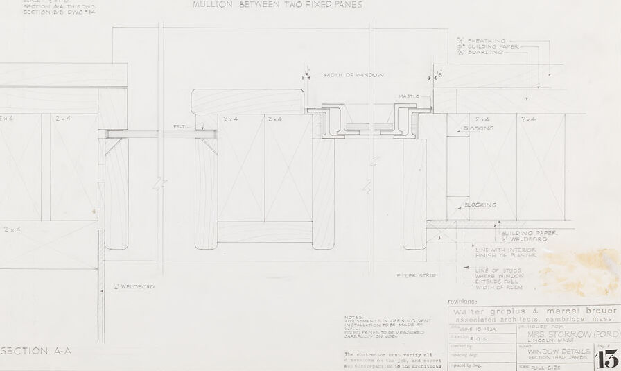
This image displays an architectural drawing featuring detailed sections and elevations of some window construction details. The drawing appears to be a blueprint or technical sketch for window installation, showing various components like mullions, blocking, and the width of elements like 2x4s. Each part of the window is labeled with precise measurements and notes, emphasizing the meticulous planning required for such a construction.
The bottom right corner of the drawing includes a title block with the project's title "WINDOW DETAILS MRS. STORROW (FORD) WINDOW REGIM", a person's name "Marcel Breuer Walter Gropius & associated architects Cambridge, Mass", and additional information like the sheet identification number "15", the scale "FULL SIZE", and a date that isn't fully visible. The title block indicates the drawing is associated with architects Marcel Breuer and Walter Gropius, who were influential figures in modernist architecture. There are also some hand-written annotations and some markings indicating revisions, suggesting that this is a working document.
The paper shows signs of age and use with some discoloration, especially noticeable in the lower right corner.
Created by gpt-4o-2024-05-13 on 2025-03-08
This image is a detailed architectural drawing of a window section, specifically illustrating the mullion between two fixed panes. The drawing comprises several views and sections, displaying both horizontal and vertical details.
Key components:
- Mullion Between Two Fixed Panes: Central detailed section showing the structure of the mullion and how it's fixed between two panes.
- Sections: Includes a typical window elevation (Section A-A, Scale 1:2) and additional close-up sections labeled with corresponding designations (e.g., Section A-A, B-B).
- Labeling and Annotation: The drawing features multiple labelled parts such as 2x4 studs, sheathing, blocking, building paper, boardings, and a mullion structure with filler strip and weld cord.
- Dimensions and Specifications: Various dimensions are clearly indicated, such as the width of the window and the specific measurements between sections.
- Associated Architects: The drawing is credited to Walter Gropius & Marcel Breuer, Associated Architects in Cambridge, Mass.
- Project Information: Noted to be for Mrs. Storrow (Ford), Concord, Mass., dated August 19, 1949, with revisions included.
The overall composition provides explicit construction details relevant for precise implementation in the field, ensuring accuracy and consistency in window assembly for the project in question.
Anthropic Claude
Created by claude-3-haiku-20240307 on 2024-12-30
This image appears to be a technical drawing or architectural plan for a window design. It shows detailed specifications and dimensions for a window frame, including the mullion (the vertical bar) between two fixed panes of glass. The drawing also includes labels and notes related to the window construction, such as the width of the window, the building paper, and the blocking. Overall, this appears to be an engineering or design document for a specific window system.
Created by claude-3-opus-20240229 on 2024-12-30
The image shows an architectural drawing or blueprint of what appears to be a wooden frame construction, likely a mullion between two fixed window panes based on the title. The drawing includes front and side views with dimensions labeled. There are notes specifying materials like "permawood" and indicating that insulation should be provided and that the design is intended to provide a thermal break between the interior and exterior. The hand-drawn sketch provides construction details for building this window mullion assembly.
Created by claude-3-5-sonnet-20241022 on 2024-12-30
This is an architectural drawing or technical blueprint showing window details and sections. The image contains detailed construction specifications for window installation, including mullions (vertical dividers) between fixed window panes. The drawing shows both elevation and section views, with measurements and annotations for various components like blocking, sheathing, and boarding. The plans appear to be drawn to scale and include specific dimensions for 2x4 framing members. At the bottom of the drawing is a title block with what appears to be architectural firm information and drawing numbers. The drawing style is typical of professional architectural documentation, with clean lines and precise technical details.
Meta Llama
Created by us.meta.llama3-2-11b-instruct-v1:0 on 2025-03-15
The image presents a technical drawing of a window, showcasing its dimensions and components. The drawing is titled "MULLION BETWEEN TWO FIXED PANES" and features a detailed diagram of the window's structure.
- Window Structure:
- The window consists of two fixed panes, separated by a mullion.
- The mullion is a vertical beam that divides the window into two sections.
- The fixed panes are rectangular in shape and have a slight curvature at the top.
- Dimensions:
- The width of the window is 2 x 4 feet.
- The height of the window is 2 x 4 feet.
- The thickness of the mullion is 2 x 4 inches.
- Components:
- The window has a frame that surrounds the panes.
- The frame is made up of four vertical posts and two horizontal beams.
- The mullion is attached to the frame using screws or nails.
- Materials:
- The window is constructed from wood, with a possible metal or plastic frame.
- The mullion is likely made of wood or metal.
- Purpose:
- The window is designed to provide natural light and ventilation to a room.
- It is also intended to provide a view of the outside environment.
In summary, the image provides a detailed technical drawing of a window, highlighting its structure, dimensions, and components. The window is designed to provide natural light and ventilation, while also offering a view of the outside environment.
Created by us.meta.llama3-2-90b-instruct-v1:0 on 2025-03-15
This image presents a detailed technical drawing of a window, showcasing its various components and dimensions. The drawing is rendered in black ink on white paper, with the title "MULLION BETWEEN TWO FIXED PANES" prominently displayed at the top center.
The drawing is divided into two main sections: the left side features a cross-sectional view of the window, while the right side provides a detailed breakdown of the window's components, including the mullion, fixed panes, and surrounding wall structure. The drawing also includes several annotations and labels, which provide additional information about the window's design and construction.
In the bottom-right corner of the image, a small table contains information about the revisions made to the drawing, including the names of the architects involved and the dates of the revisions. Overall, this image provides a comprehensive and detailed representation of a window's design and construction, making it a valuable resource for architects, builders, and other professionals in the field.
Amazon Nova
Created by amazon.nova-lite-v1:0 on 2025-01-12
This architectural drawing shows a detailed section of a building's exterior wall, focusing on the construction of a window frame. The drawing includes dimensions and specifications for various components, such as the mullion between two fixed panes, the width of the window, and the materials used, including sheathing, building paper, and boarding. The drawing also notes that the window panels are to be made of welded glass and that the exterior finish is to be plaster. The drawing is signed by Walter Gropius and Marcel Breuer, who were associated architects for the project.
Created by amazon.nova-pro-v1:0 on 2025-01-12
The image appears to be a detailed architectural blueprint or drawing. It shows a section of a building, specifically labeled as "Section A-A," which is a common notation in architectural drawings to indicate a vertical cut through the structure. The drawing includes measurements, annotations, and specific details about the construction materials and methods. There are sections labeled with dimensions, such as "2x4" and "3x4," indicating the size of certain structural elements. The drawing also includes notes about the construction process, such as "Mull between two fixed panes" and "Sheathing building paper boarding." The blueprint is likely part of a larger set of plans for a building project, providing detailed instructions for the construction team.
Text analysis
Amazon